
9 posts tagged with "Seeed Studio"

Seeed Studio

View All Tags

FeedMyFurBabies – Send and Receive MQTT messages between AWS IoT Core and your micro-controller – I am switching from Arduino CPP to MicroPython

· 7 min read
Chiwai Chan
Tinkerer

Recently I switched my Cat Feeder project's IaC to AWS CDK in favour of increasing my focus and productivity on building and iterating, rather than constantly mucking around with infrastructure everytime I resume my project after a break; which is rare and far between these days.

Just as with coding IoT microcontrollers such as the ESP32s, I want to get straight back into building every opportunity I get; so I am also switching away from Arduino based microcontroller development written in C++ - I don't have a background in C++ and to be honest this is the aspect I struggled with the most because I tend to forget things after not touching it for 6 months or so.

So I am switching to MicroPython to develop the logic for all my IoT devices going forward, this means I get to use Python - a programming lanaguge I work with frequently so there is less chance of me being forgetful when I use it at least once a month. MicroPython is a lean and efficient implementation of the Python 3 programming language that includes a subset of the Python standard library and is optimized to run on microcontrollers and in constrained environments - a good fit for IoT devices such as the ESP32!

What about all the Arduino hardware and components I already invested in?

Good news is MircoPython is supported on all ESP32 devices - based on the ones I myself have purchased; all I need to do to each ESP32 device is to flash it with a firmware - if you are impatient, you can scroll down and skip to below to the flashing the firmware section. When I first started Arduino, MicroPython was available to use, but that was 2 years ago and there were not as many good blog and tutorial content out there as there is today; I couldn't at the time work out how to control components such as sensors, servos and motors as well as I could with C++ based coding using Arduino; nowdays there are way more content to learn off and I've learnt (by PoCing individual components) enough to switch to MicroPython. As far as I understand it, any components you have for Arduino can be used in MicroPython, provided that there is a library out there that supports it, if there isn't then you can always write your own!

What's covered in this blog?

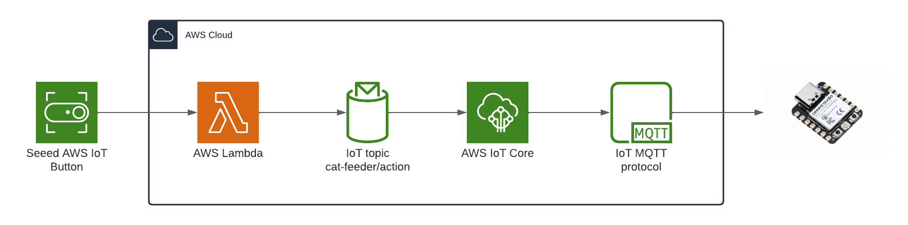
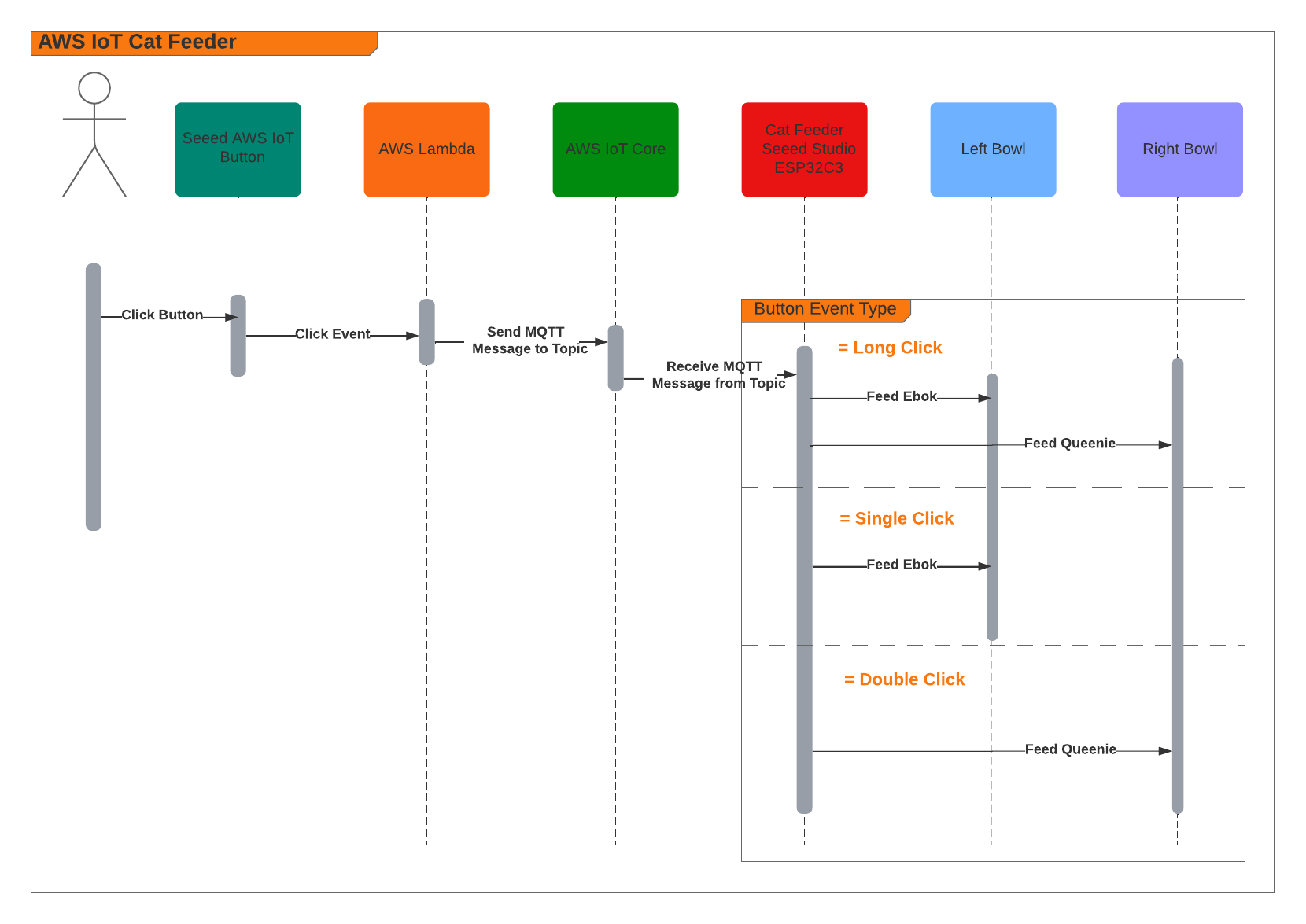
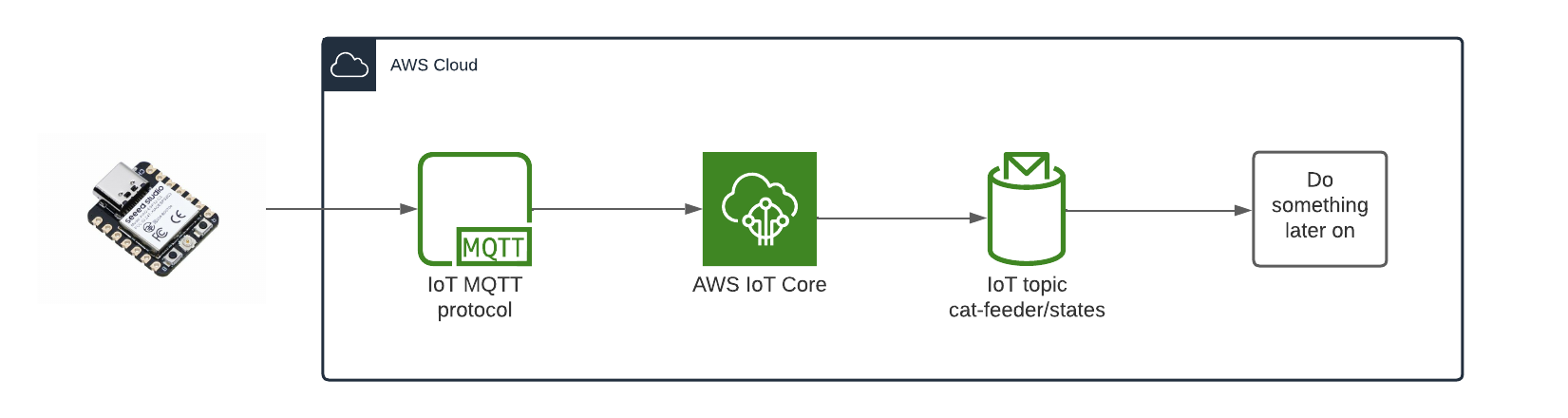
By the end of this blog, you will be able to send and receive MQTT messages from AWS IoT core using MicroPython, I will also cover the steps involved in flashing a MicroPython firmware image onto an ESP32C3. Although this blog has a focus and example on using an ESP32, this example can be applied to any micro-controllers of any brand or flavours, provided the micro-controller you are using supports MicroPython.

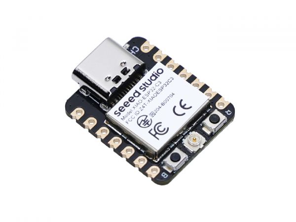
Flashing the MicroPython firmware onto a Seeed Studio XIAO ESP32C3

Seeed Studio XIAO ESP32C3

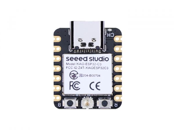
The following instructions works for any generic ESP32C3 devices!

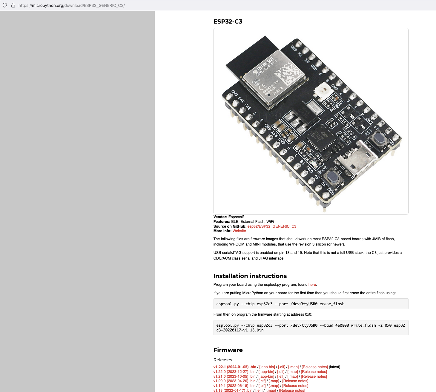
Download the latest firmware from micropython.org

https://micropython.org/download/ESP32_GENERIC_C3/

MicroPython firmware esp32c3

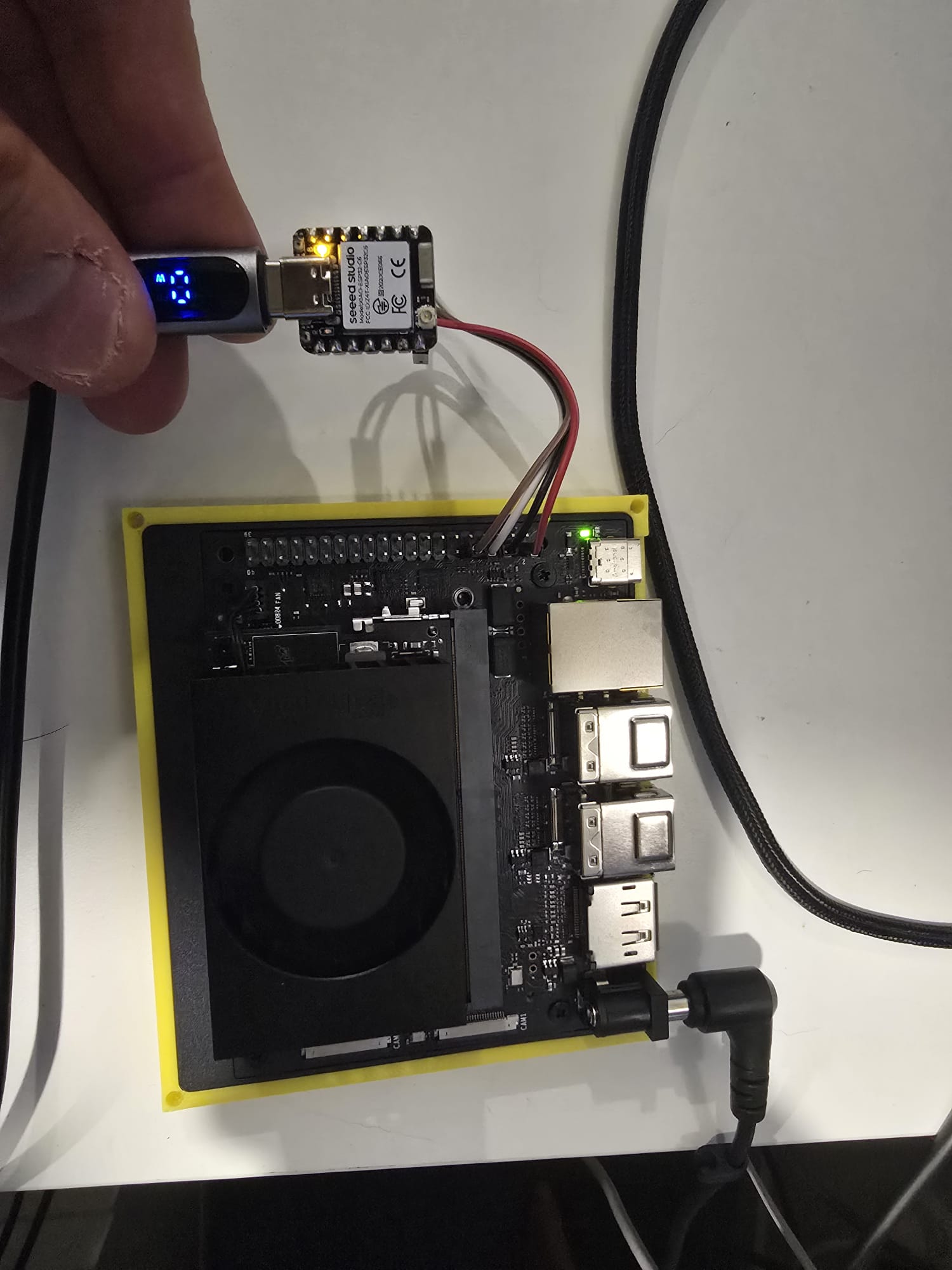
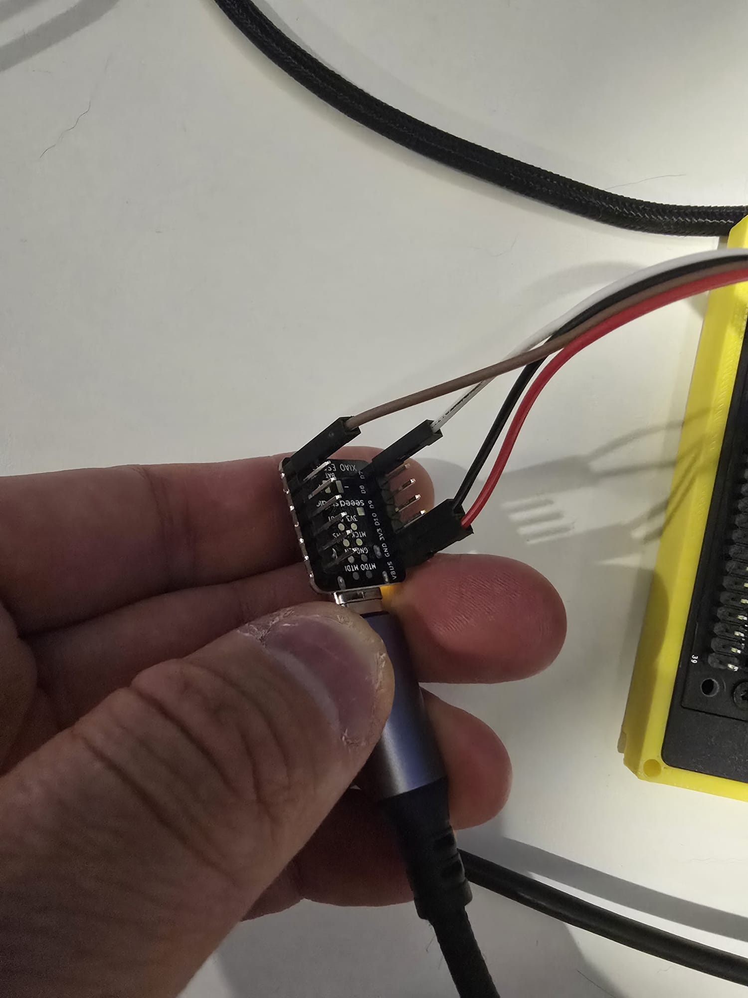
Next, I connected my ESP32C3 to my Mac and ran the following command to find the name of the device port

 /dev/ttyUSB0

Find port device

My ESP32C3 is named "/dev/tty.usbmodem142401", the name for your ESP32C3 may be different.

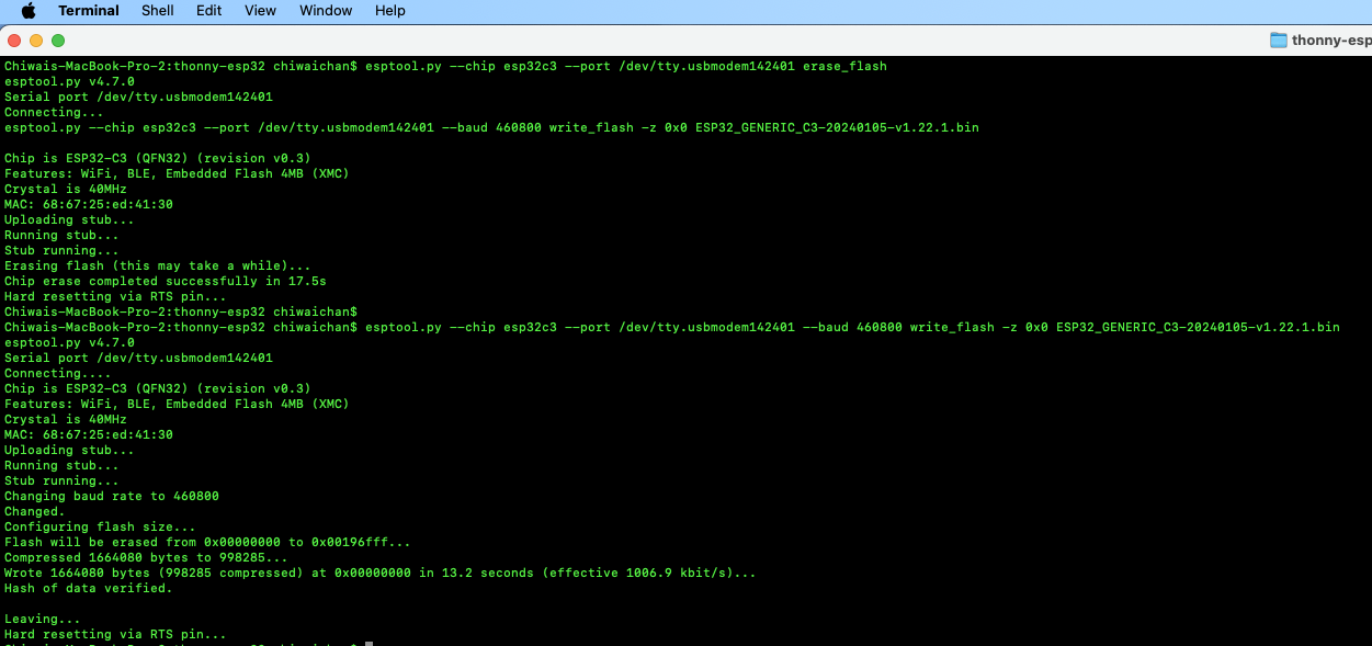
Next, install esptool onto your computer, then run the following commands to flash the MicroPython firmware onto the ESP32C3 using the bin file you've just downloaded.

esptool.py --chip esp32c3 --port /dev/tty.usbmodem142401 erase_flash

esptool.py --chip esp32c3 --port /dev/tty.usbmodem142401 --baud 460800 write_flash -z 0x0 ESP32_GENERIC_C3-20240105-v1.22.1.bin

It should look something like this when you run the commands.

esptool Flashing Firmware

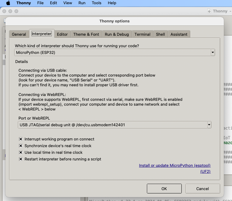
Install Thonny and run it. Then go to Tools -> Options, to configure the ESP32C3 device in Thonny to match the settings shown in the screenshot below.

esptool Flashing Firmware

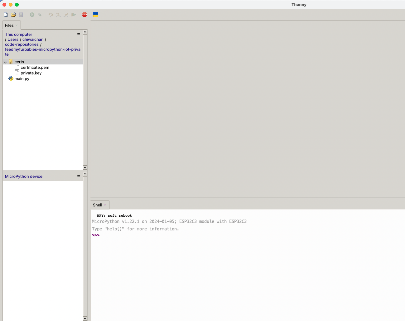
If everything went well, you should see these 2 sections in Thonny: "MicroPython Device" and "Shell", if not then try clicking on the Stop button in the top menu.

Thonny MicroPython Device

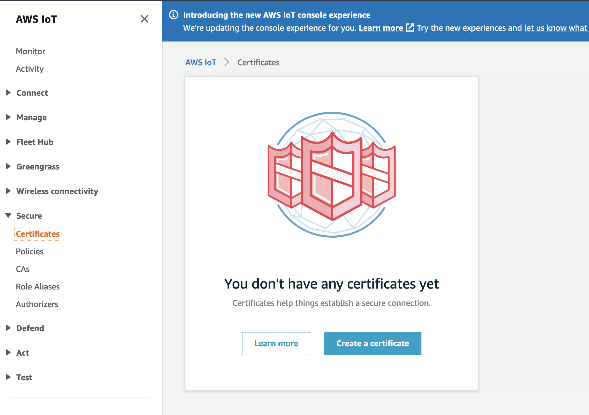
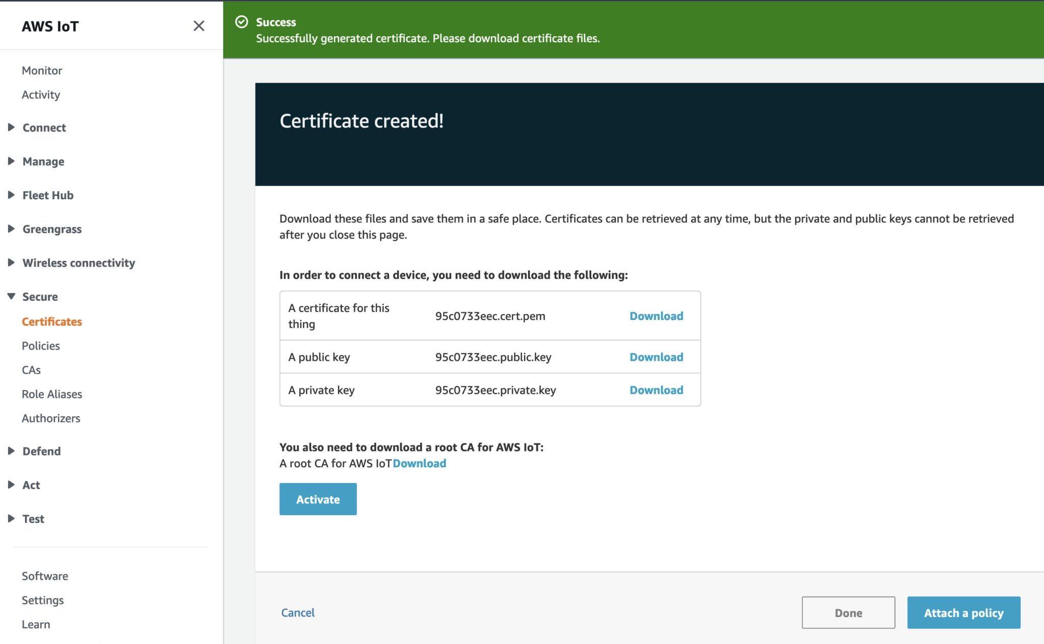
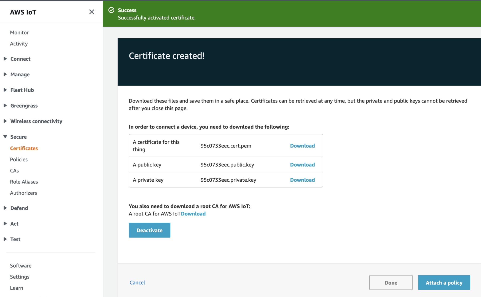
AWS IoT Core Certificates and Keys

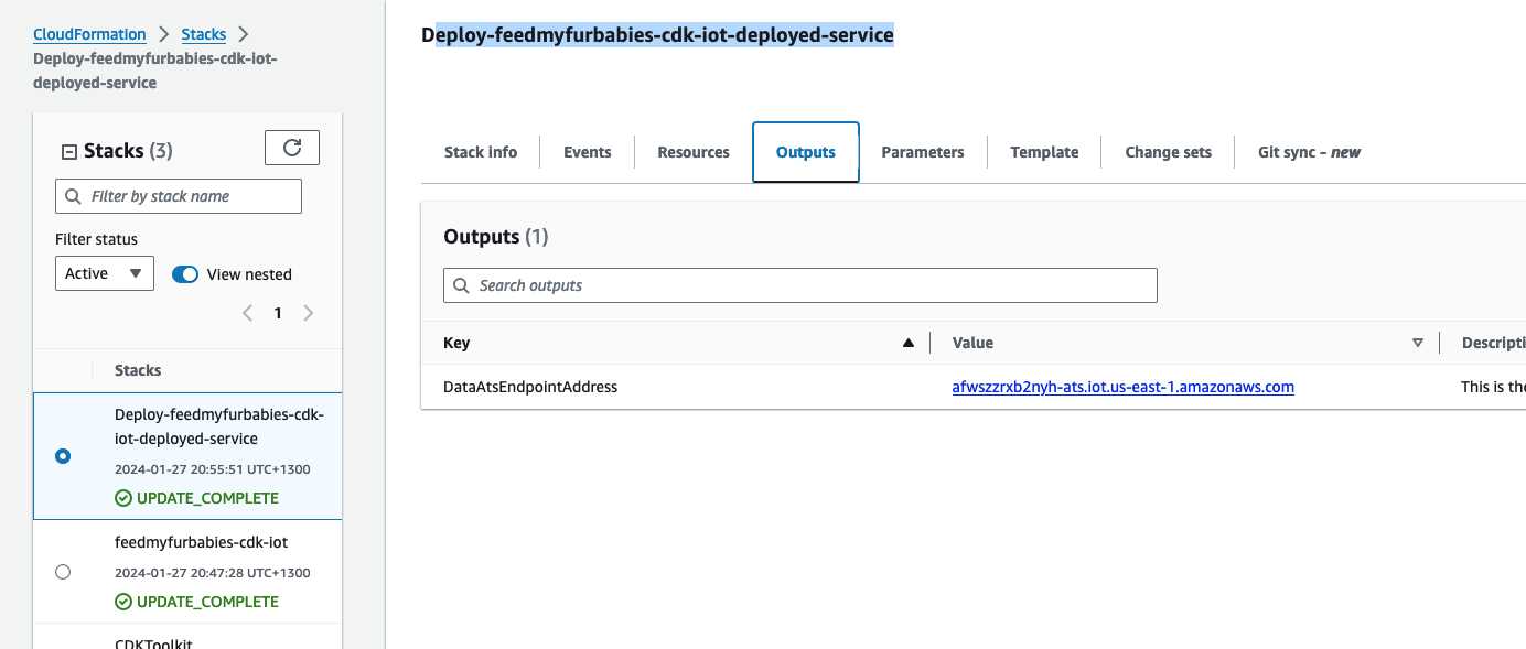
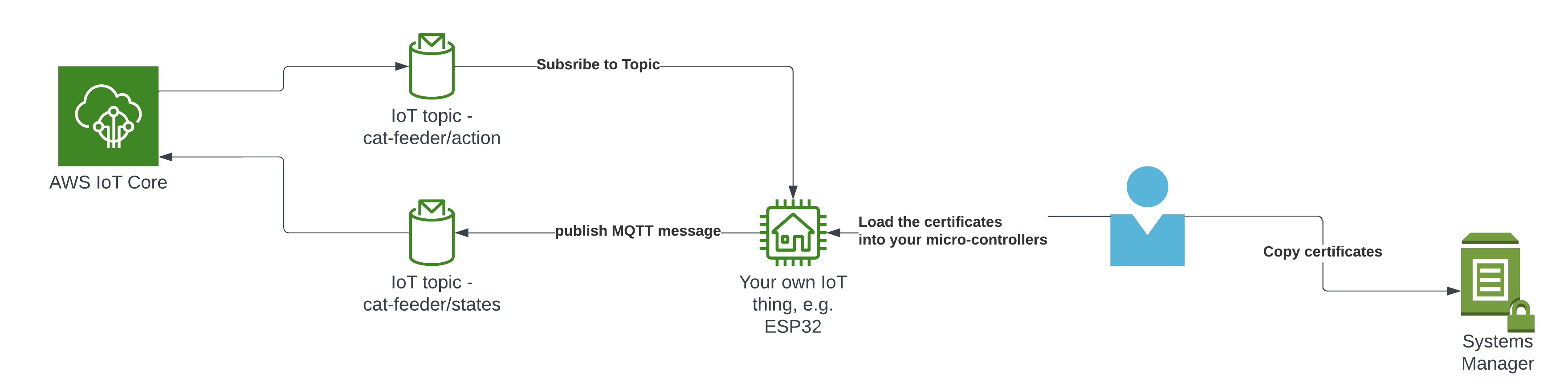
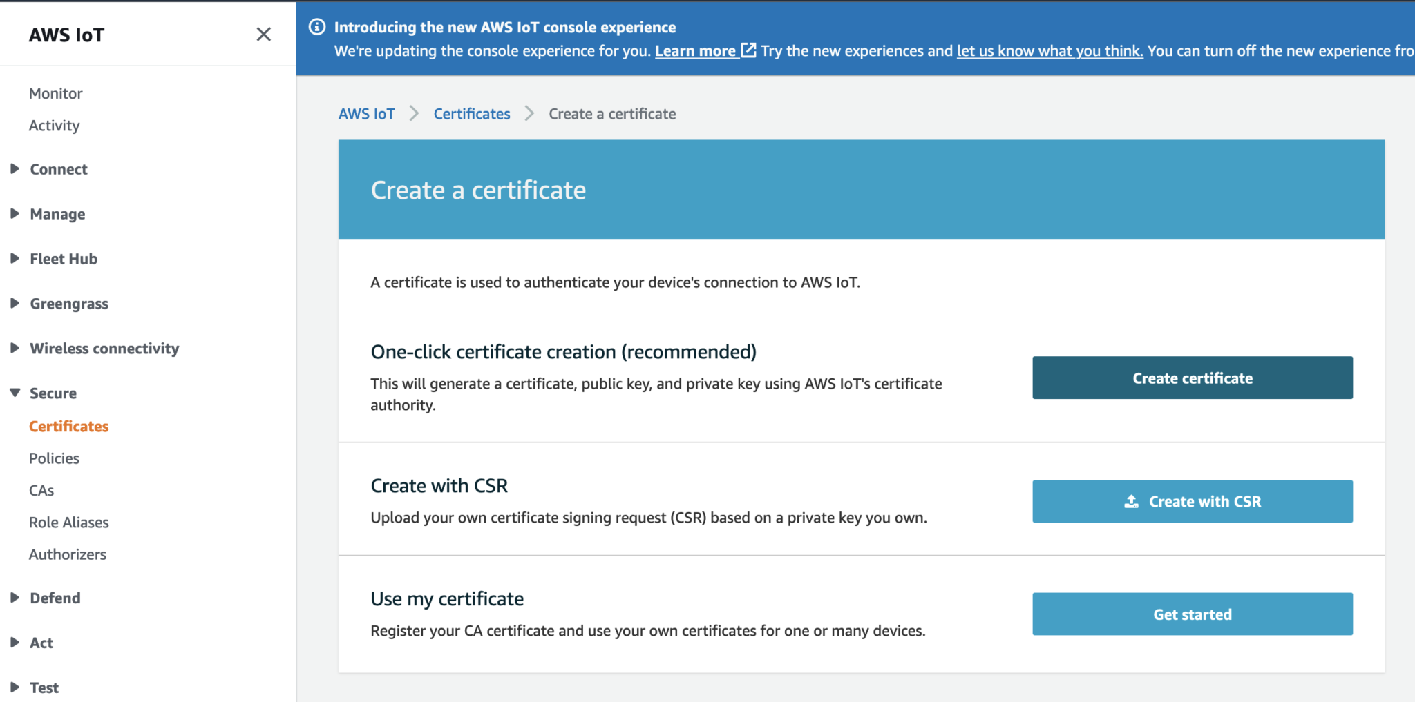
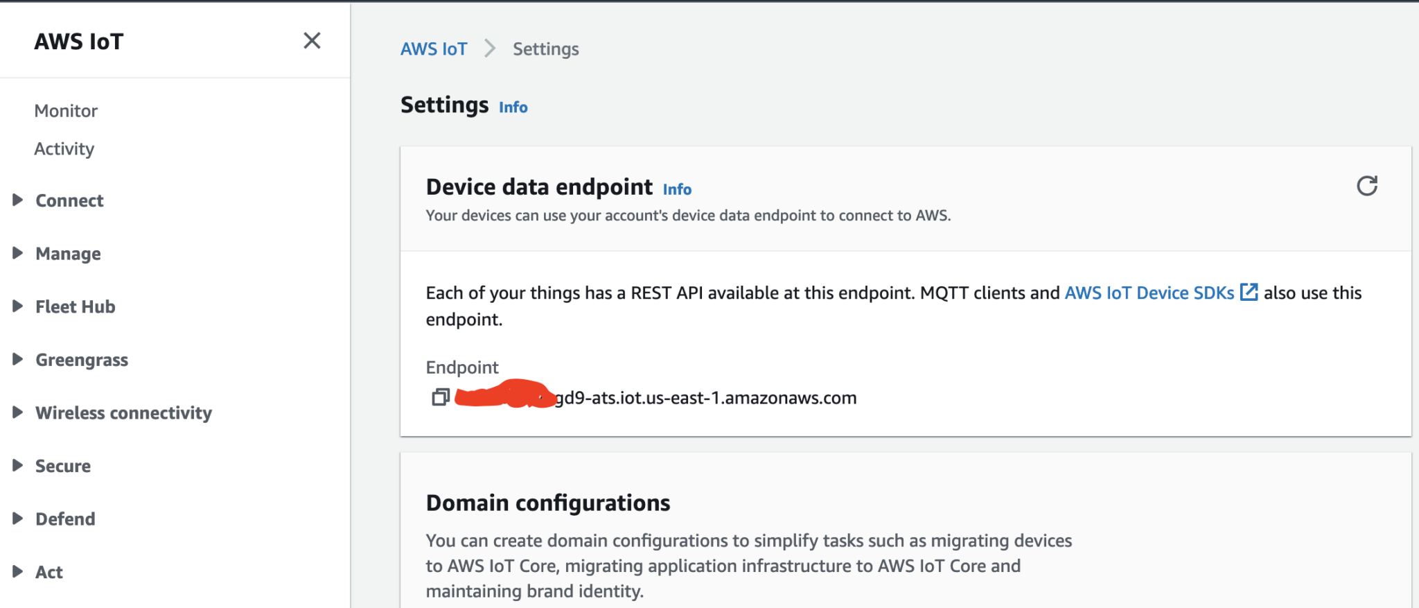
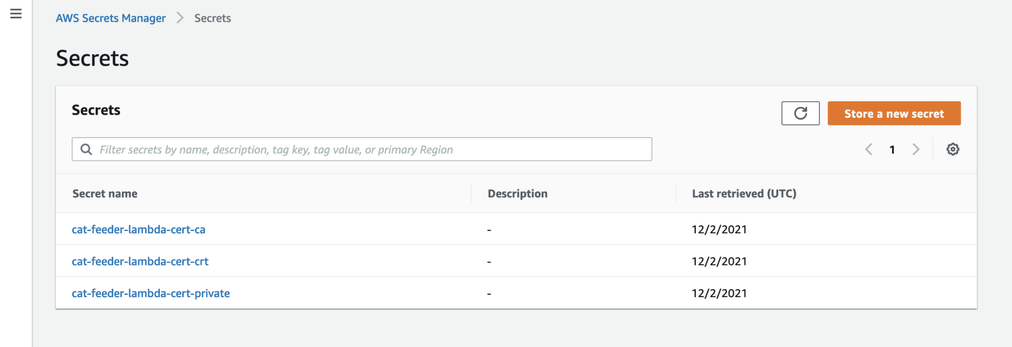
In order to send MQTT messages to an AWS IoT Core Topic, or to receive a message from a Topic in reverse, you will need a set of Certificate and Key\s for your micro-controller; as well as the AWS IoT Endpoint specific to your AWS Account and Region.

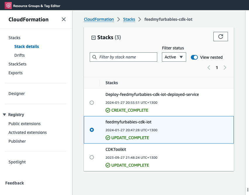
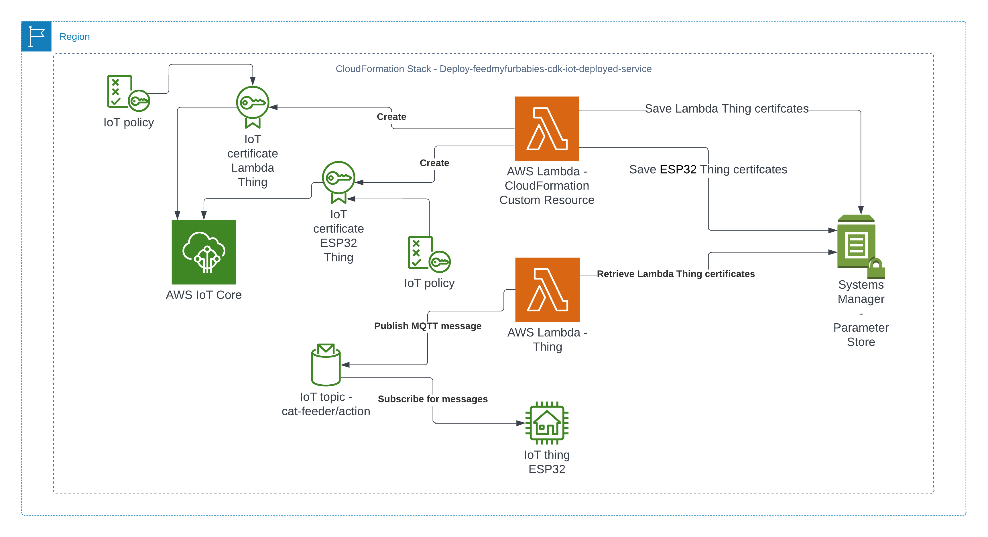
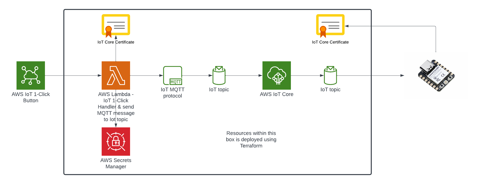
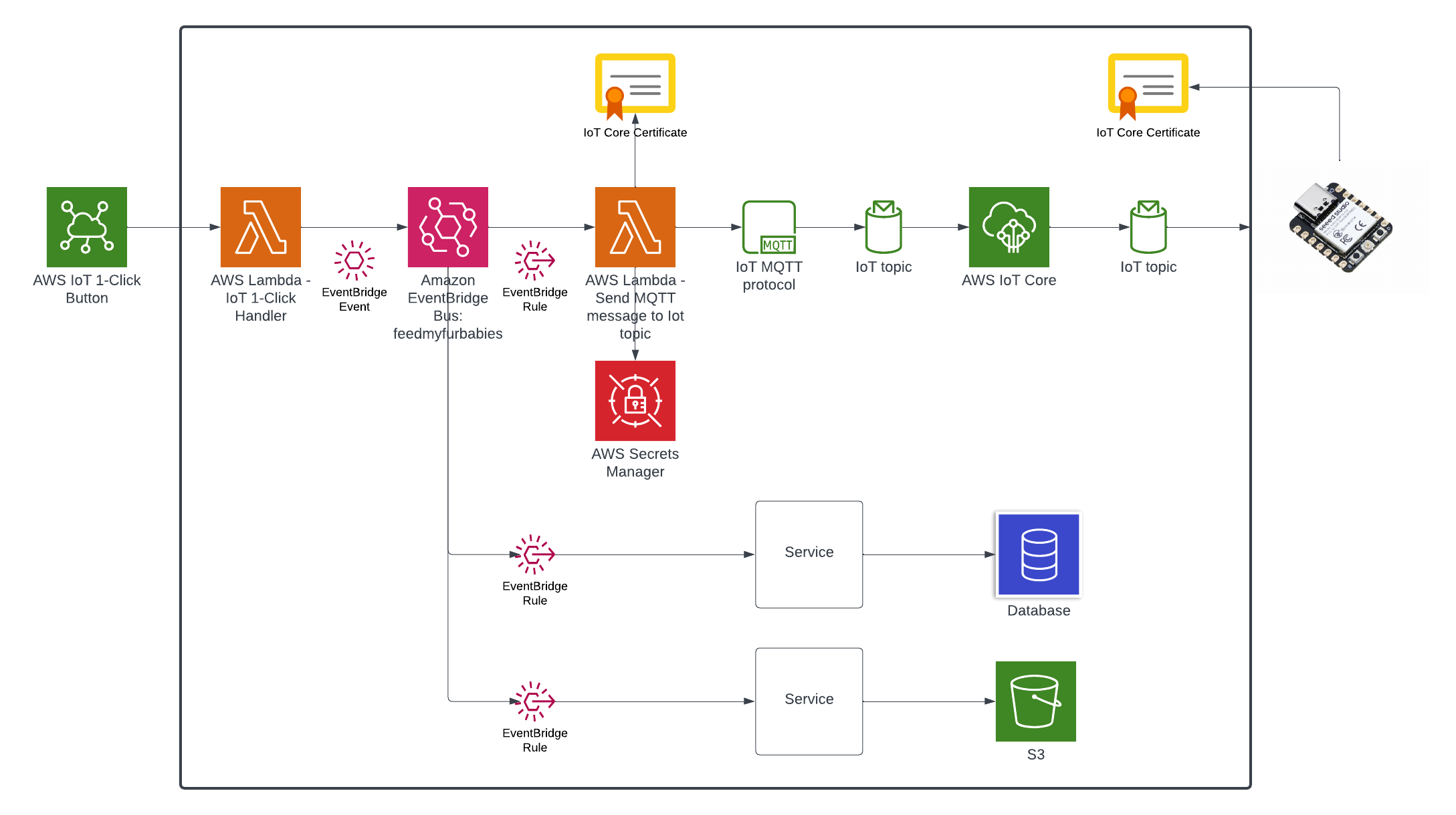
It's great if you have those with you so you can skip to the next section, if not, do not worry I've got you covered. In a past blog I have a reference architecture accompanied by a GitHub repository on how to deploy resources for an AWS IoT Core solution using AWS CDK, follow that blog to the end and you will have a set of Certificate and Key to use for this MicroPython example; the CDK Stack will deploy all the neccessary resources and policies in AWS IoT Core to enable you to both send and receive MQTT messages to two separate IoT Topics.

Reference AWS IoT Core Architecture: https://chiwaichan.co.nz/blog/2024/02/02/feedmyfurbabies-i-am-switching-to-aws-cdk/

Upload the MicroPython Code to your device

Now lets upload the MicroPython code to your micro-controller and prepare the IoT Certificate and Key so we can use it to authenticate the micro-controller to enable it to send and receive MQTT messages between your micro-controller and IoT Core.

Clone my GitHub repository that contains the MicroPython example code to publish and receive MQTT message with AWS IoT Core: https://github.com/chiwaichan/feedmyfurbabies-micropython-iot

It should look something like this.

GitHub repo

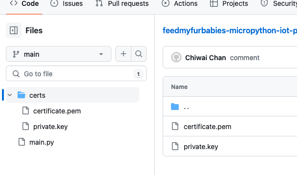
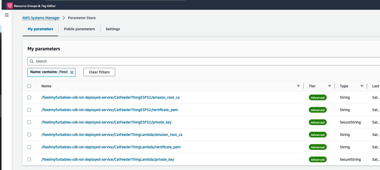
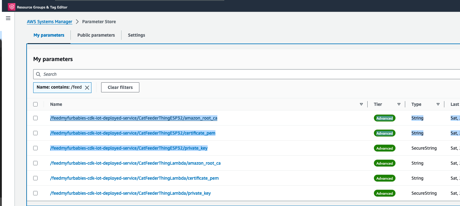
Copy your Certificate and Key into the respective files shown in the above screenshot; otherwise, if you are using the Certificate and Key from my reference architecture, then you should use the 2 Systems Manager Parameter Store values create by the CDK Stack.

Systems Manager Parameter Store values

Next we convert the Certificate and Key to DER format - converting the files to DER format turns it into a binary format and makes the files more compact, especially neccessary when we run use it on small devices like the ESP32s.

In a terminal go to the certs directory and run the following commands to convert the certificate.pem and private.key files into DER format.

openssl rsa -in private.key -out key.der -outform DER
openssl x509 -in certificate.pem -out cert.der -outform DER

You should see two new files with the DER extension appear in the directory if all goes well; if not, you probably need to install openssl.

Systems Manager Parameter Store values

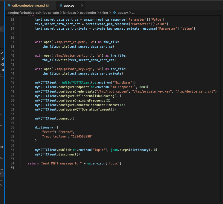
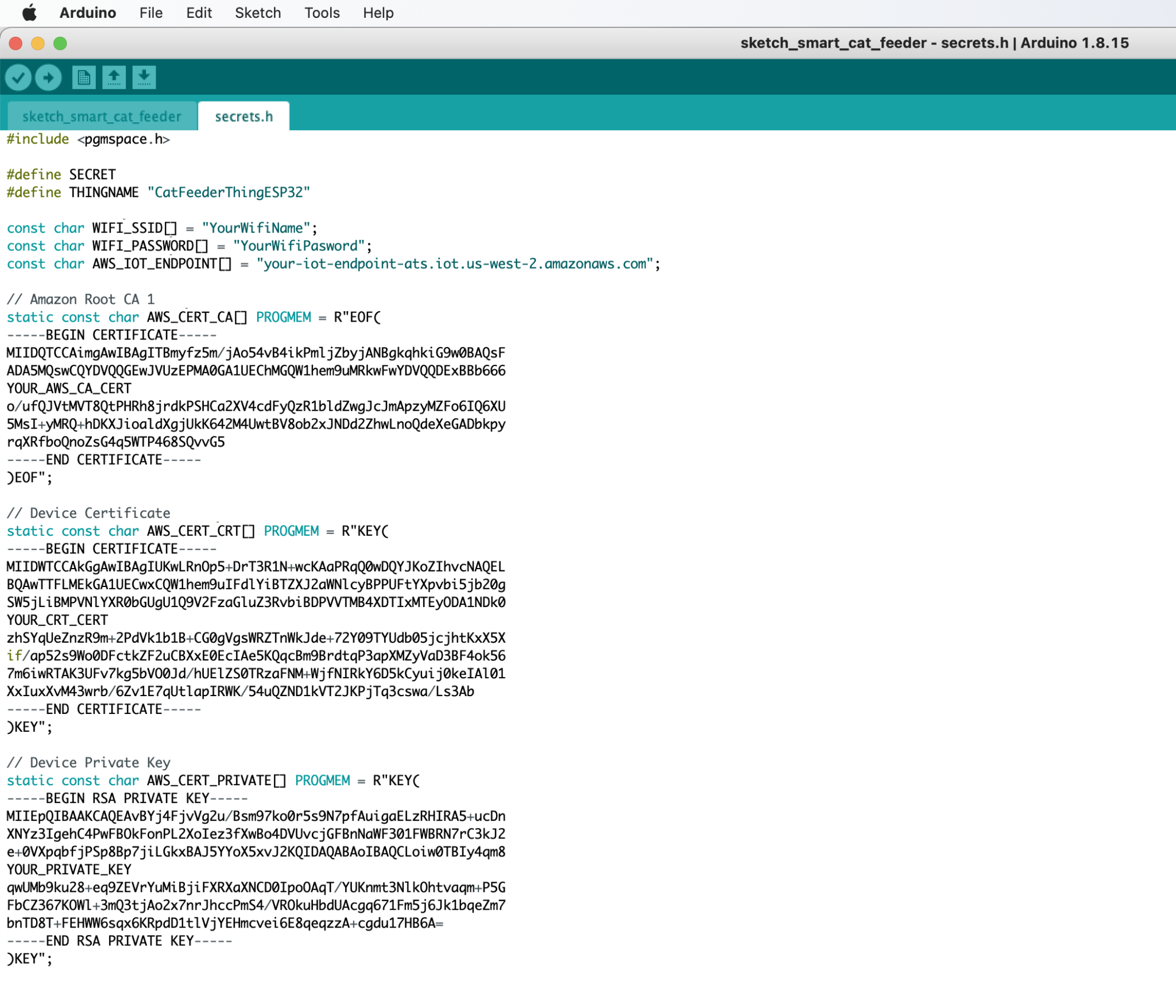
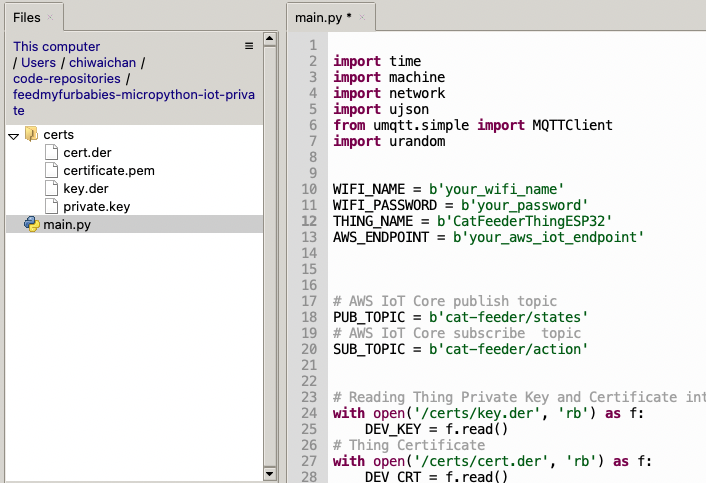
In Thonny, in the Files explorer, navigate to the GitHub repository's Root directory and open the main.py file. Fill in the values for the variables shown in the screenshot below to match your environment, if you are using my AWS CDK IoT referenece architecture then you are only required to fill in the WIFI details and the AWS IoT Endpoint specific to your AWS Account and Region.

Wifi and iot Core Settings

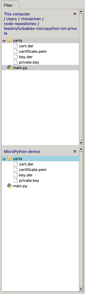
Select both the certs folder and main.py in the Files explorer, then right click and select "Upload to /" to upload the code to your micro-controller; the files will appear in the "MicroPython Device" file explorer.

Upload files to Thonny

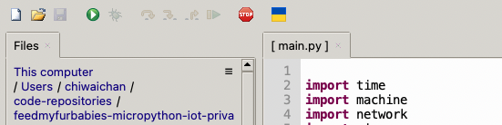
This is the moment we've been waiting for, lets run the main.py Python script by clicking on the Play Icon in green.

Run main

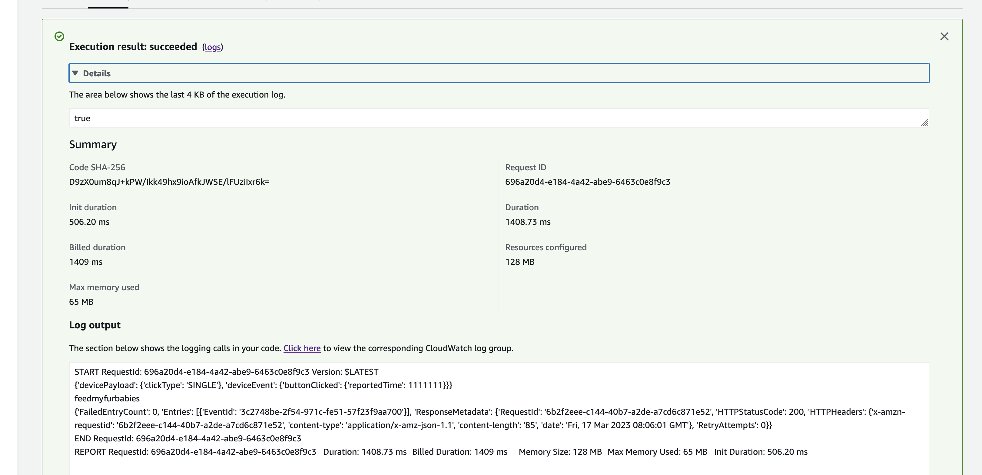
If all goes well you should see some output in the Shell section of Thonny.

Thonny Shell

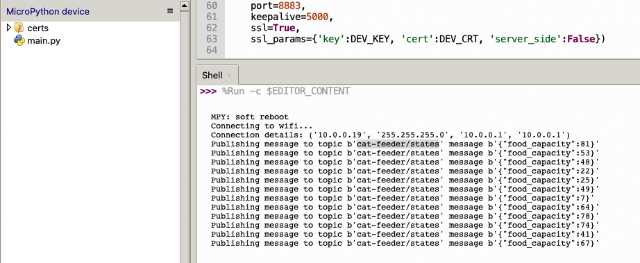
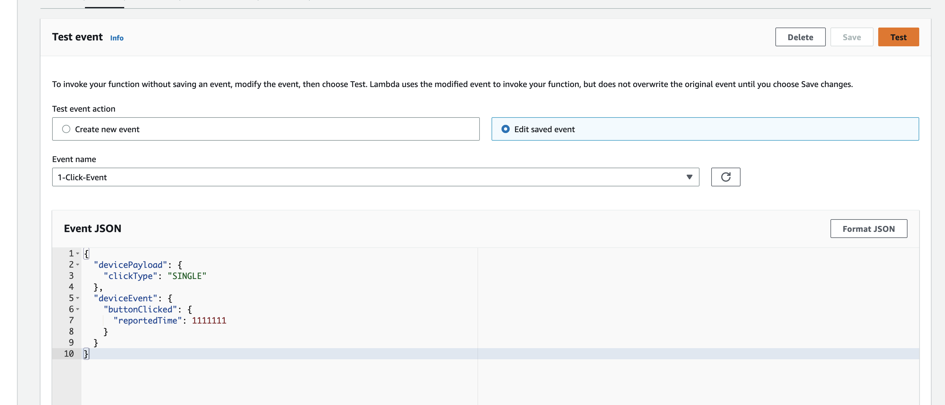
The code in the main.py file has a piece of code that is generating a random number for the food_capacity percentage property in the MQTT message; you can customise the message to fit your use case.

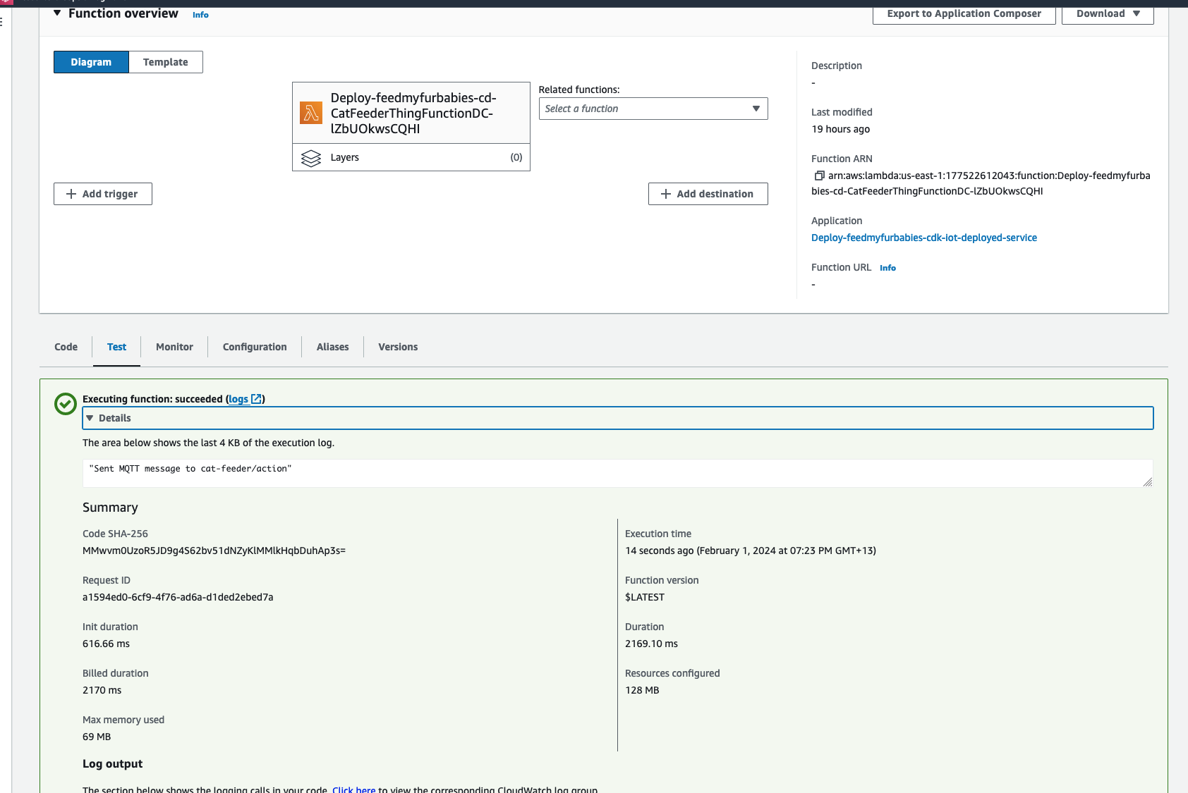
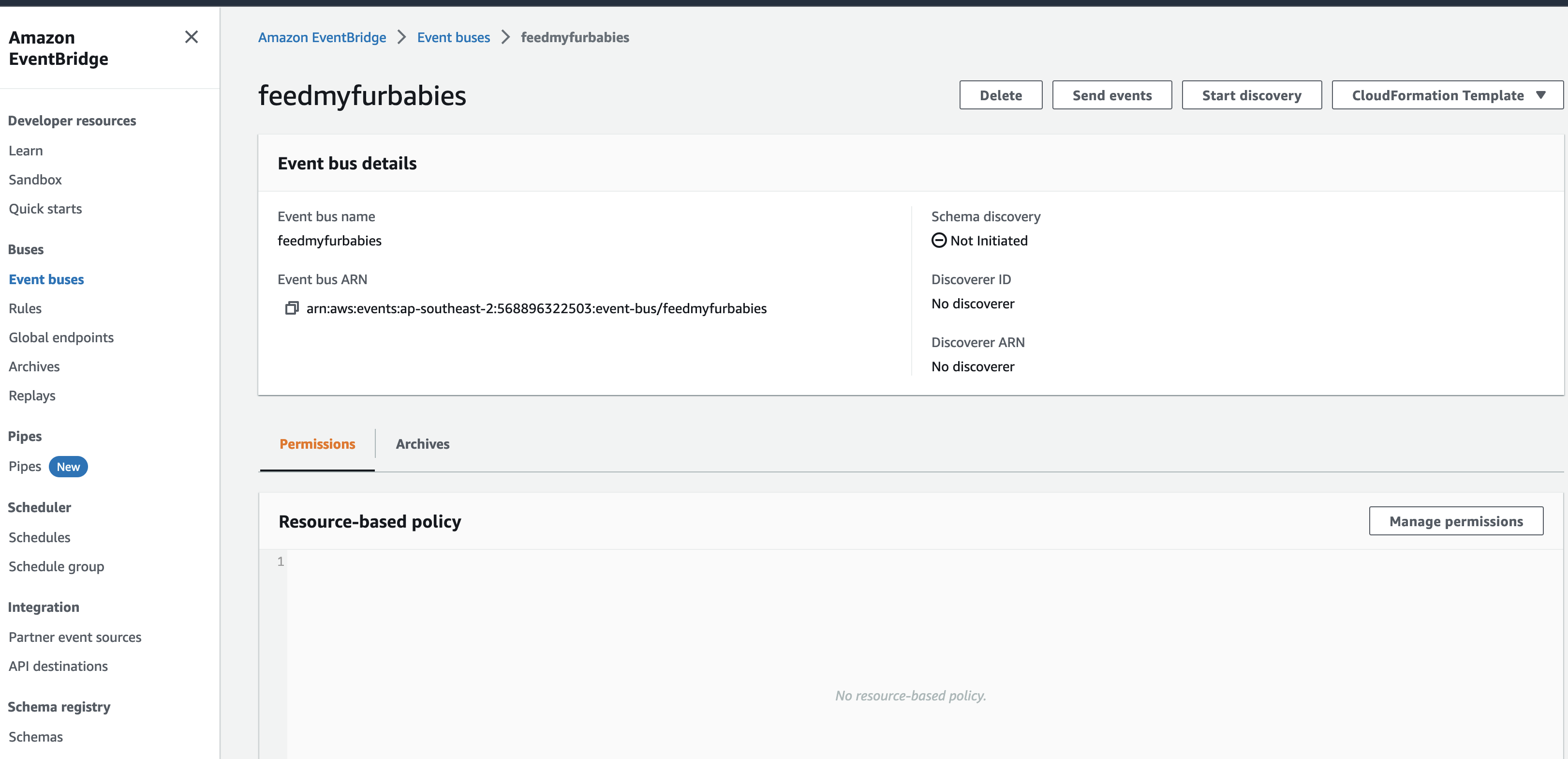
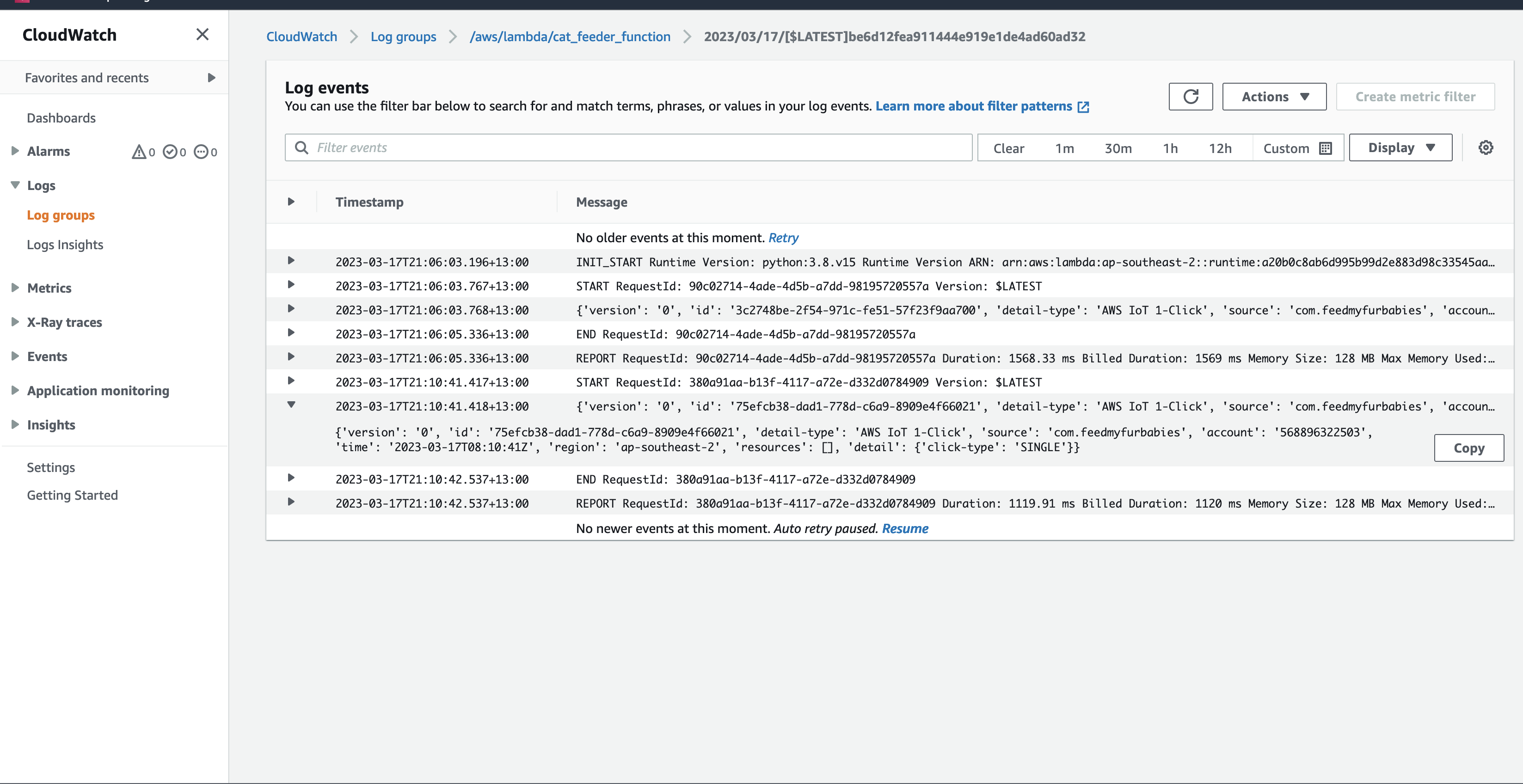
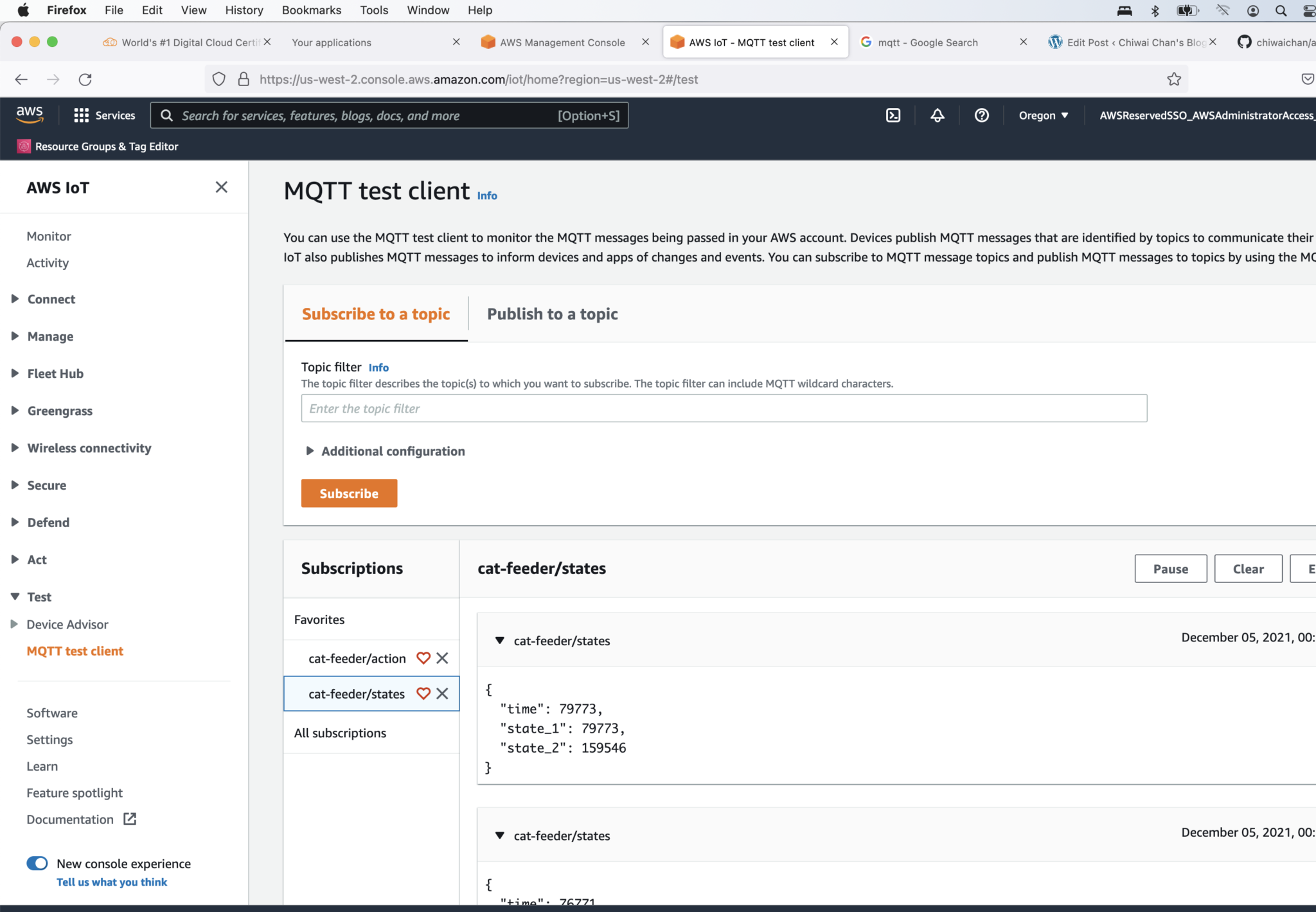
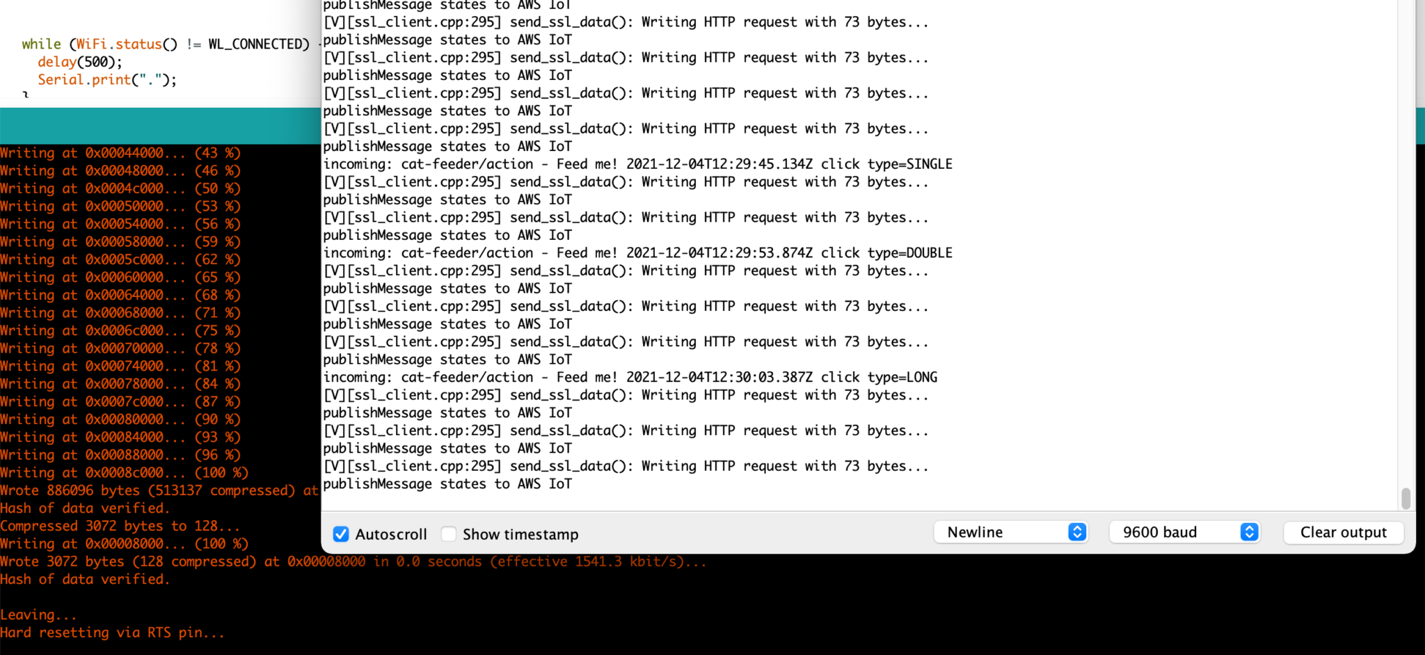
But lets verify it is actually received by AWS IoT Core.

aws iot mqtt test client

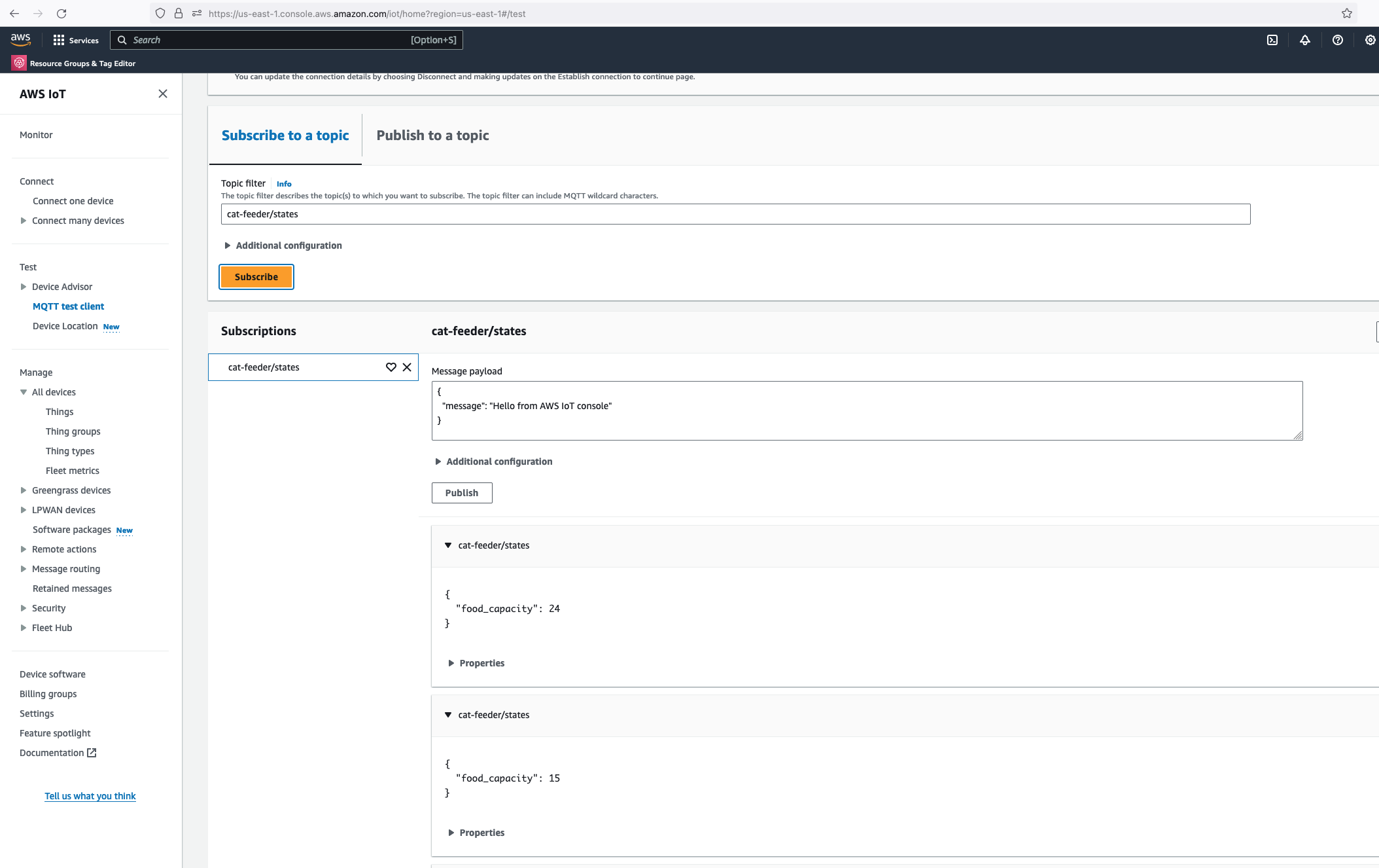
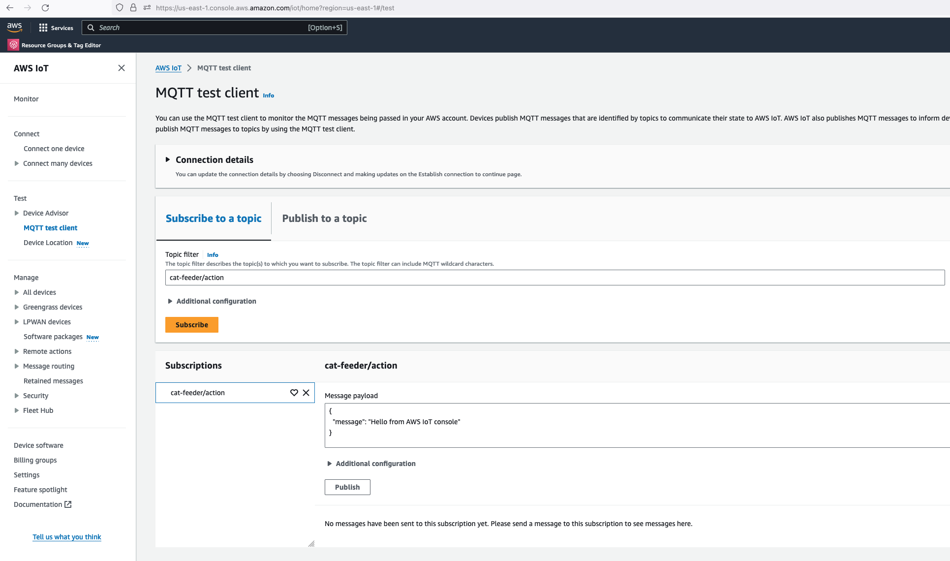
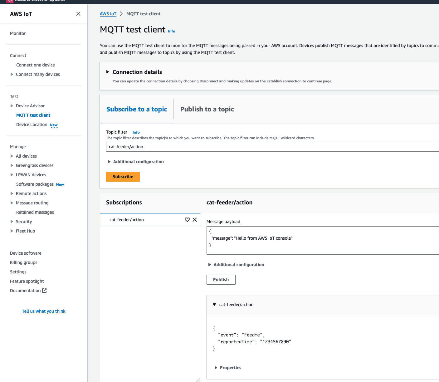
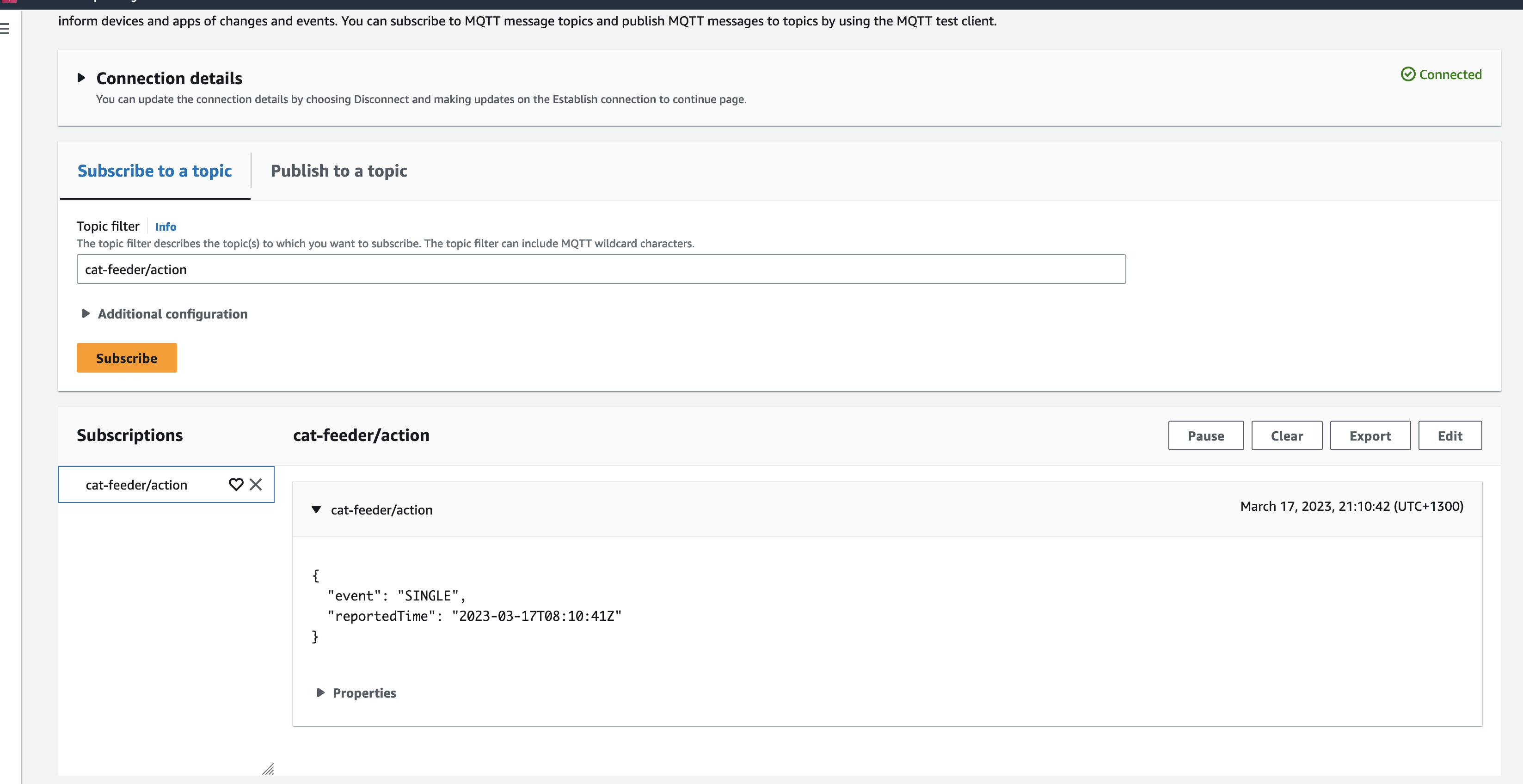
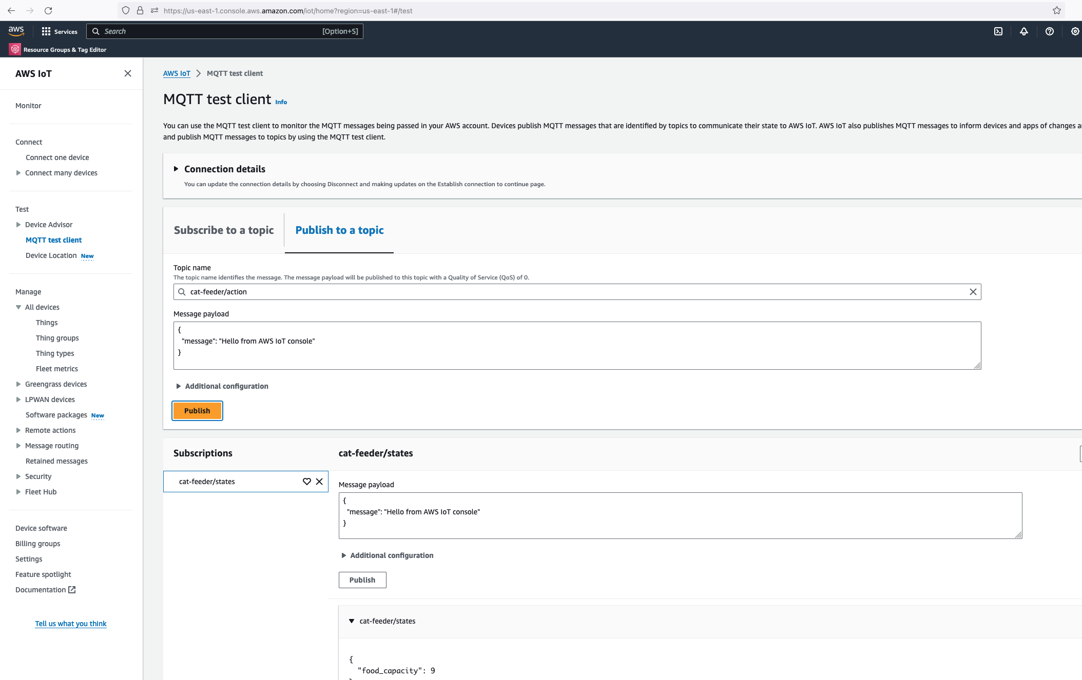
Alright, lets go the other way and see if we can receive MQTT messages from AWS IoT Core using the other Topic called "cat-feeder/action" we subscribed to in the MicroPython code.

Lets go back the AWS Console and use the MQTT test client to publish a message.

publlish mqtt from aws

thonny message received

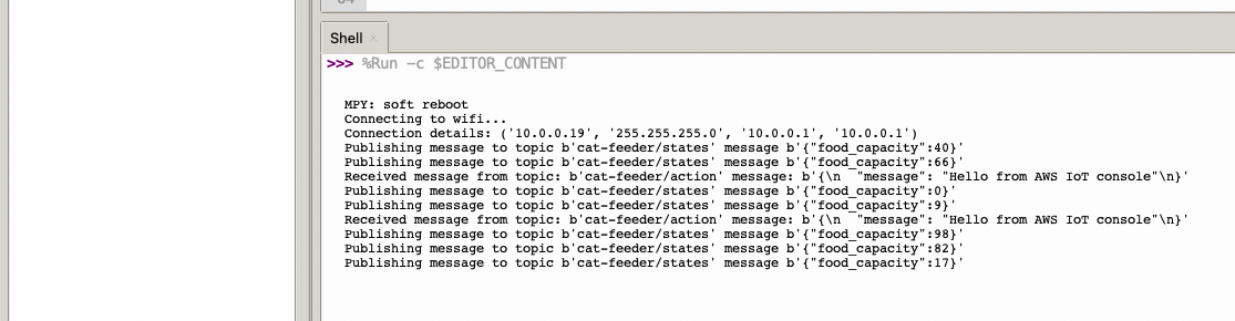
In the Thonny Shell we can see the message "Hello from AWS IoT console" sent from the AWS IoT Core side and it being received by the micro-controller.

FeedMyFurBabies – I am switching to AWS CDK

· 7 min read
Chiwai Chan
Tinkerer

I have been a bit slack on this Cat Feeder IoT project for the last 12 months or so; there have been many challenges I've faced during that time that prevented me from materialising the ideas I had - many of them sounded a little crazy if you've had a conversation with me in passing, but they are not crazy to me in my crazy mind as I know what I ramble about is technically doable.

Examples of the technical related challenges I had were:

  • CloudFormation: the initial version of this project was implemented using CloudFormation for the IaC, here is the repository containing both the code and deployment instructions. If you read the deployment instructions, you will notice there are a lot of manual steps required - e.g. creating 2 sets of certificates in AWS Iot Core in the AWS Console; and copying and pasting values to and from the CloudFormation Parameters and Outputs, even though at the time I made my best efforts to minimise the manual effort required while coding them. It was not a good example to get it up and running especially if you are new to AWS, Arduino or IoT; as I myself struggled at times to deploy my own example.

  • Terraform: I ported the CloudFormation IaC code to Terraform some time last year, you can find it here. Nothing is wrong with Terraform itself; I just keep forgetting to save or misplaced my terraform state files every time I resume this project. In reality I might leverage both Terraform and CDK for the projects/micro-services I create in the future, but it all really depends on what I am trying to achieve at the end of the day.

Deploying the AWS CDK version of this Cat Feeder IoT project

So, the commands below are the deployment instructions taken from the AWS CDK version of this project, you can find it here: https://github.com/chiwaichan/feedmyfurbabies-cdk-iot

git clone git@github.com:chiwaichan/feedmyfurbabies-cdk-iot.git
cdk feedmyfurbabies-cdk-iot
cdk deploy

git remote rm origin
git remote add origin https://git-codecommit.us-east-1.amazonaws.com/v1/repos/feedmyfurbabies-cdk-iot-FeedMyFurBabiesCodeCommitRepo
git push --set-upstream origin main

The commands above are all you need to execute in order to deploy the Cat Feeder project in CDK - assuming you have the AWS CDK and your AWS credentials configured on the machine you are calling these commands on; the first group of commands checks out the CDK code which deploys an AWS CodeCommit repository and a CodePipeline pipeline - creates the 1st CloudFormation Stack using a CloudFormation template; and the second group of commands pushes the CDK code into the newly created CodeCommit repository created in the first group of commands, which in turns trigger an execution in CodePipeline and the pipeline deploys the resources for this Cat Feeder IoT project - creates the 2nd CloudFormation Stack using a different CloudFormation template.

The two groups of commands creates the 2 CloudFormation Stacks shown in the screenshot below, the stack "feedmyfurbabies-cdk-iot" provisions the CodeCommit repository and CodePipeline - using the 1st CloudFormation template, and the stack "Deploy-feedmyfurbabies-cdk-iot-deployed-service" provisions the resources for this Cat Feeder IoT project - using the 2nd CloudFormation template.

CloudFormation Stacks

FYI, I did not come up with the pattern I just described above that deployed the two CloudFormation Stacks: one for the pipeline and the other for the AWS resources for this Cat Feeder IoT project; I only came across it during one of those AWS online workshops I was using to learn CDK and noticed this pattern and found it useful, and pretty much decided to adopt it for my projects going forward.

Test out the deployed solution

The resources that are relevant to architecture of this AWS IoT solution are shown in the diagram below.

Deployed resources

There are 2 sets of certificates and 2 sets of AWS IoT Things and policies deployed by the "Deploy-feedmyfurbabies-cdk-iot-deployed-service":

IoT Certificates

The 1st set of certificates and IoT Thing is hooked up to the AWS Lambda function (Lambda Thing) shown in the diagram, this Lambda function acts as an AWS IoT Thing (uses the certificates saved in Systems Manager Parameter prefixed with "/feedmyfurbabies-cdk-iot-deployed-service/CatFeederThingLambda") and is fully configured as one along with all the neccessary certificates and permissions to send an MQTT message to the "cat-feeder/action" topic in AWS IoT Core; this is a very convenient way to see in action how one could send MQTT messages to AWS IoT Core using Python, as well as a good way to confirm the deployment was successful by testing it out!

Before we invoke the Lambda Thing/function, we need to subscribe to the "cat-feeder/action" topic so that we could see the incoming messages sent by the Lambda function.

Subscribe to IoT Topic

Then we invoke the Lambda function in the AWS Console:

Lambda Result

Make sure you get a green box confirming the MQTT message was sent.

The code in the Lambda is written in Python and it sends a JSON payload (the dictionary variable shown in the code below) to the IoT Topic "cat-feeder/action"

Lambda Code

Now lets go back to AWS IoT Core to confirm we have received the message:

AWS IoT Core MQTT received

We can see the message received in IoT Core is the dictionary object sent by the Lambda code

Conclusion

Using CDK does not eliminate all the issues you might encounter when using CloudFormation - I have a future blog on creating and using CloudFormation Custom Resources lined up; because at the end of the day CDK just generates a CloudFormation template and handles the deloyment of the CloudFormation Stack for you without you having to manage the CloudFormation Stacks or templates; the intent of this blog is to demonstrate how little effort is required to deploy an AWS IoT solution using CDK, compared with the same architecture I shared in my Github repo 2 years ago but with instructions using a CloudFormation template deployment that was long and tedious in manual steps.

The ultimate aim of change in IaC is to just focusing on building and iterating!

I do often talk too much in my blogs, but in this instance the instructions to deploy this solution for yourself to try out is very minimal, with the majority of the content focused on the resources deployed; and what each resource is for and how they interact with each other.

Extra

You may have noticed that there are 2 sets of certificates deployed in IoT Core and 2 IoT Things in this reference architecture, this is because you can take the 2nd set of certificates (prefixed with "/feedmyfurbabies-cdk-iot-deployed-service/CatFeederThingESP32") and Thing provisioned purely for you to send MQTT message to AWS IoT Core from your own IoT hardware devices / micro-controllers.

Your own Thing

If you want to try it out, you will need to use the IoT Core Endpoint specific to your AWS Account and Region; you can either find it in the AWS IoT Core Console, or copy it from the CloudFormation Stack's Output:

IoT Core Endpoint

The Lambda Thing we tested above can be used to send MQTT messages to your own IoT device/micro-controller, as the 2nd set of certificates is configured with the neccessary IoT Core Policies to receive the MQTT messages sent to the Topic "cat-feeder/action", and the certificates is also configured with the policies to send MQTT messages to a second IoT Topic called "cat-feeder/states"

Your own Thing Architecture

I have a future blog that will demonstrate how to do this using MicroPython and a Seeed Studio XIAO ESP32C3 - so watch this space.

FeedMyFurBabies – Event-Sourcing using Amazon EventBridge

· 8 min read
Chiwai Chan
Tinkerer

In my previous AWS IoT Cat feeder project I used a Lambda function as the event handler each time the Seeed Studio AWS IoT 1-click button was pressed, the Lambda function in turn published an MQTT message to AWS Iot Core which is received by the Cat Feeder (via a Seeed Studio XIAO ESP32C3 micro-controller) to dispense food into either one of the cat bowls or both (depending on the type of press performed on the IoT button). The long term goal is to integrate the AWS IoT Cat Feeder with the Feed My Fur Babies project.

In this Part 2 of the Feed My Fur Babies blog series, I will be introducing the Event-Sourcing pattern to the https://www.feedmyfurbabies.com architecture; describe the benefits of designing an architecture around Event-Souring and an example implemented using Terraform. I recently learnt Terraform and I now prefer it over the native IaC.

Current state architecture

Here is the current state of the Cat Feeder architecture amd the IoT related resources previously deployed in AWS using CloudFormation:

Current State Architecture

The responsibilities of each of the resources deployed in the diagram prior to the introduction of the Event-Sourcing pattern into the architecture are:

  • AWS IoT 1-Click Button: This is an IoT button I physically press to emit an event to dispense food into one or both of the cat bowls, this button can be used anywhere where there is a WIFI connection
  • AWS IoT Core Certificates: Certificates are associated with resources and devices that interacts with the AWS IoT Core Service, either publishing an MQTT message to an AWS IoT Topic, or receiving an MQTT message from a Topic
  • AWS Lambda - IoT 1-Click Event Handler & sends an MQTT message to an Iot topic: This Lambda function is responsible for handling incoming events created by the AWS IoT 1-Click Button, as well as translating the event into an MQTT message before sending it to an AWS IoT Core Topic. This is the component in the architecture that is the main focus of this blog post, we will describe how this component will be re-architectured and decomposed to work in conjunction with the introduction of the Event-Sourcing pattern.
  • AWS IoT Core: This is the IoT service that manages the IoT Topics and Subcriptions to said Topics
  • Seeed Studio XIAO ESP32C3: a micro-controller subscribed to the IoT Topic (the one the Lambda sent MQTT messages to) that will dispense food into 1 or 2 cat bowls when it receives an MQTT message from the Topic

For further details on what role this architecture plays in the Smart IoT Cat Feeder, visit Part 2 of the Smart Cat Feeder Blog Series.

What is Event-Sourcing?

The idea of Event-Sourcing is to capture all events that occurs within a system during its lifetime, these events are stored in an immutable ledger in the sequence in which they occurred in.

One of the biggest benefits of capturing all the events of a system is that we are able to replay every single event that has ever occured within the system (partially or as a whole) at a later time (lets say 5 years later), and have the ability to selectively replay the 5 years worth of events to one or more specific downstream event bus targets: an event bus target could be a new application that was deployed into your production environment 5 years after the first event was created; what this means is that we could hydrate this new application's datastore with 5 years worth of data as if it existed at the beginning when the first event occured. Also, imagine being able to re-create entire datastores with the full history for 100s of applications (where each application has its own datastore) within your system landscape, these datastores could be hydrated with the full history of events stored in the immutable Event-Sourcing ledger, or even replay the events that occur from the very first event and up to a specific event at a given point in time (e.g. half of the entire ledge) - effectively providing you with the ability to create any datastore in any datastore engine with the data inside in a state to any given point in time.

How do we introduce Event-Sourcing into the architecture?

Step 1

We start off with the AWS Lambda function shown in the current state architecture where its responsibilites is to handle the events received from the AWS IoT 1-Click Button each time it is pressed, as well as sending an MQTT message to an AWS Iot Core Topic in response to each incoming event; essentially it has 2 distinct responsibilities


Step 2

Next, we decompose the single Lambda function into 2 separate distinct Lambda functions based on its 2 responsibilities, then we chain the 2 Lambda functions together to preserve its functionality - what we have effectively achieved by doing this is decoupling the 2 responsibilities as 2 separate units of work - resulting in 2 separate compute resources.

The benefits by a decoupled architecture are:

  • Each of the Lambda functions can be implemented in different languages - e.g. one in Python and the other can be in Java
  • Independent release cycles for each of the Lambda functions
  • Changes to either one of the 2 responsibilities can be made independently of each other
  • Each Lambda function can be scaled independently of another

Step 3

In this step we use Amazon EventBridge as the Event-Sourcing store - known as the immutable ledger we described earlier, we will also leverage EventBridge as a serverless event bus to help us receive, filter, transform, route and deliver events to downstream services (event bus targets). In this instance we will slip EventBridge in between the 2 Lambda functions and we will be storing every single IoT event sent by the IoT Button into the immutable ledge,

Benefits of adding EventBridge to the architecture:

  • The IoT 1-Click Lambda handler no longer directly calls the downstream Lambda function - so it is unaware of the downstream targets
  • The IoT events are stored in an immutable ledger in the sequence in which they occurred in
  • Prepare the system landscape with the ability to more easily develop micro-services in an Event-Driven architecture using the orchestration pattern

Target State Architecture

Target State Architecture

This is the end result of introducing Event-Sourcing to the architecture; it may not look like much benefits has been gained from adding Amazon EventBridge - in fact one might think that we've added more components and in effect created more moving parts and complexity. But I have decided to specifically introduce this very early into the architecture as an investment so that I am in a position to rapdily build out my micro-service architecture - reaping the rewards from the get go.

Try it out for yourself

I have created a GitHub Repository to deploy a complete working example of the resources shown in the Target State Architecture using Terraform.

I suggest you deploy this to have a play for yourself:

  1. Clone the repository: "git clone git@github.com:chiwaichan/feedmyfurbabies-202303-eventsourcing-using-eventbridge.git"
  2. Setup your Terraform environment
  3. Run: "terraform init && terraform apply"

Also, check out each individual resource deployed by this Terrafrom code.

Create a test IoT 1-Click event to pass the event end-to-end through all the deployed resources

This is the IoT 1-Click Lambda function handler shown in the AWS Console

1-Click Handler Lambda

Create a test event so we can invoke the Lambda function to simulate an event as if a physical IoT Button is pressed

1-Click Handler Lambda - Test Event

Here we can view the logs for this Lambda function Test invocation

1-Click Handler Lambda - Test Event

The IoT 1-Click Lambda function handler sends an Event to the Custom EventBridge Event Bus named "feedmyfurbabies"

EventBridge Event Bus

The event sent to the Custom Event Bus matches on the "source" attribute with a value of "com.feedmyfurbabies" with the Custom Event Bus Rule named "feeds-rule"

EventBridge Event Bus Rule

This Lambda function is the downstream target of the Custom Event Bus Rule that was mactched by the event and is responsible for interpreting the event message and translate it into an MQTT message, then in turn sends it to the AWS IoT Core Topic "cat-feeder/action" that you can subscribe to using a micro-controller, e.g. Seeed Studio XIAO ESP32C3.

Send MQTT Message Lambda

Send MQTT Message Lambda - Monitoring

Here we can see the logs of the event received by the EventBridge Custom Bus Rule

Send MQTT Message Lambda - Logs

In the AWS Console for the AWS Iot Core Service, we can subscribe to Topics to receive an MQTT message right at the end of the downstream services - this is useful if you don't use a micro-controller

IoT Core - MQTT Client Subscribe Topic

Future State Architecture

Future State Architecture

We end up with an architecture that will enable us to easily add targets to consume events managed by the EventBridge Custom Event Bus, doing so in a way where the IoT 1-Click Lambda function has no knowledge of any newly created subscribers of the Custom Event Bus.

In a future blog I will demonstrate this.

4×4 fun with a bit of Iot, vlogging and Machine Learning – Part 1

· 7 min read
Chiwai Chan
Tinkerer

Jimny

Months prior to the very first lockdown I had gotten myself on the waitlist for a 4x4 Jimny, so I could take it to the beach without worrying about getting beached like I likely would in a regular front wheel drive hatchback; or take it to the bushes to climb some hills and see how far I would get without flipping it (badly). Knowing I wouldn't be able to drive it for an long indefinitely amount time so I decided to cancel the order back then; in some ways I was sad then but in many ways I am happy now that I have had a fair amount of time to have a good think about what else I could do with the Jimny whilst taking it on these adventures.

The time spent mulling has lead to another new blog series; this will take on a similar build approach I took while building my Iot Cat Feeder, but this time it will be on a larger scale in terms of the amount of moving parts and components; also, I would get to enjoy myself this time instead of the cats. For those that are unfamiliar with the approach I took in my prior build, I will start the blog series by proposing an idea I have in mind with a certainty of about 70% of achieving a functional prototype - this is mainly due to not having the background nor experience on most of the skills required to build out this idea.

Generally, I would create a new Part for the Blog Series as I achieve a milestone during the build, where I talk about what was achieved in the milestone and provide the details on how I got there; where possible I would include a public Github repository for any code written for the build.

So enough of my rumbling.

What is it that I am wanting to build?

As you may have already predicted what is involved in this build from the image above, yes it will involve a 4x4 - I have a Jimny on the way; and some cloud buzz words like Iot and Machine Learning.

The goals of this build is to:

  • Develop a solution to capture video recordings of my 4x4 adventures of the entire journey with 5+ viewpoints around the vehicle in 4K resolution, realistically I might only be about to capture full HD videos as explained further down this blog.
  • Capture and store the vehicle's telemetries at regular intervals as the vehicle is driven using the CAN Bus protocol, e.g. speed, RPM of the engine and any other states the car is in.
  • Capture other useful data not monitored by the vehicle's CAN Bus, such as GPS co-ordinates and the environment where the vehicle is at during the time - e.g. temperature, humidity, luminosity and many more using hand picked sensors.
  • Ingest in real time all the videos, CAN Bus and sensor data captured into an AWS Datalake

4x4

If I were able to achieve all the goals in the list above, then I would like to also achieve these goals:

  • Create a Digital Twin using AWS TwinMaker of the Jimny and associate all the sensors and devices captured with it
  • Train Machine Learning models using the data ingest in the AWS Datalake
  • Do something with the AWS Deeplens sitting in my draw for the past year with the ML models created above, perhaps warn me I am able to do something that will cause the Jimny to land on its roof like last time by making predictions on an ML model.
  • Have some sort of cloud solution that spits out a video for each of my trips so I can use it to upload to YouTube, with the video displaying some of the telemetries and sensor data captured.

AWS

At the end of the blog series I will conclude whether I was able build something that was functional, and whether or not I was able to achieve all the goals I have stated in the 2 lists above.

Where I am in terms of progress for this build?

It has been a bit of a challenge to source certain types of electronic components at the moment as some may already know, so I've only managed to source the majority of components required at this point in time.

So far I have source the following components:

Starlink RV

I had been wanting one of these for a long time so when I saw it on special I jumped on it straight away. This is the RV version so it means it can be taken anywhere with me, so I will mount this on a roof rack - one reason why I do not want to have the Jimny on its roof because it would not be fun to be somewhere with no internet for a long period of time.

Randy

The ideal location to place the Starlink is in a spot with no obstruction and as far away from everything as possible, however, when I tested it out in my tiny back yard with it sitting in the center surrounded by 2 houses (both 2 stories) and a high fence, I got the following results:

Starlink RV SpeedTest

Although the speed is as fast as you get on the one of the slowest fibre plan available in New Zealand, the upload speed is the ultimate factor that determines how many live feeds we can ingest into the Datalake; a 4K resolution video is 20Mbps so that does not leave much bandwidth for all of the other data types, results may be better depending on where I am at the time, and also, unless Starlink offers symmetrical upload speeds then we are forced with full HD feeds, FYI download speeds can be as high as 500Mbps in some parts of the world. One option is to store the data onto a NAS drive via the Home Assistant installed on the LinkStar - a device similar to a Raspberry PI, then upload the videos into the Datalake after I get home - I like to avoid this as it is too much admin.

Router / Wifi

Got a few lying around at house doing nothing.

Cameras

I also have some spare cameras to use; the feed on these can be served using the RTSP protocol, I also have a few ESP32-CAMs I recently purchased so this build will use a combination of the 2 camera types. Most webcams can be used for this.

Seeed Studio XIAO ESP32C3

I have a bunch of these as they are my go tos when I build projects using micro-controllers; they are like $5 USD: Seeed Studio XIAO ESP32C3, one of, if not the smallest ESP32s I've come across and is more reliable than other ones I've used previously.

Seeed Studio XIAO ESP32C3

I also have various sensors for use that measures:

  • Distance from objects
  • Temperature
  • Sound
  • Humidity
  • Luminosity
  • CO2

Seeed Studio LinkStar with Home Assistant

Seeed Studio LinkStar

I'll be using this to pull the feeds from the cameras, as well as saving the videos onto a NAS if we go down that route.

What is left to source?

  • Seeed Studio WIO ESP32 CAN - this is a kit I'll be using to interface with the CAN Bus to retrieve telemetries from the Jimny.
  • Jimny

Next blog

The next blog in this series I will take all the components I currently have and link it all up and detail what and how I got there.

Smart Cat Feeder – Part 4

· 5 min read
Chiwai Chan
Tinkerer

This is the Part 4 and final blog of the series where I detail my journey in learning to build an IoT solution.

Please have a read of my previous blogs to get the full context leading up to this point before continuing.

  • Part 1: I talked about setting up a Seeed AWS IoT Button
  • Part 2: I talked about publishing events to an Adruino Micro-controller from AWS
  • Part 3: I talked about my experience of using a 3D Printer for the first time to print a Cat Feeder

Why am I building this Feeder?

I've always wanted to dip my toes into building IoT solutions beyond doing what a typical tutorial teaches in only turning on LEDs - I wanted to build something that would used everyday. Plus, I often forget to feed the cats while I am away from home (for the day), so it would be nice to come home to a non-grumpy cat by feeding them remotely any time and from any where in the world using the internet.

What was used to build this Feeder?

  • A 3D Printer using PLA as the filament material.
  • An Arduino based micro-controller - in this case a Seeed Studio XIAO ESP32C3
  • A couple of motors and controllers
  • AWS Services
  • Seeed AWS IoT Button
  • Some code
  • and some cat food

So how does it work and how is it put together?

To simply describe what is built, the Feeder uses an Iot button click to trigger events over the internet to instruct the feeder to dispense food into one or both food bowls.

cat feeder

Here are some diagrams describing the architecture of the solution - the technical things that happens in-between the IoT button and the Cat Feeder.

architecture diagram seeed sequence diagram

When the Feeder receives a MQTT message from the AWS IoT Core Service, it runs the motor for 10 seconds to dispense food into either one of food bowls, and if the message contains an event value to dispense food into both bowls we can run both motors concurrently using the L298N controller.

Here's a video of some timelapse picture captured during the 3 weeks it took to 3D print the feeder.

The Feeder is made up of a small handful of basic hardware components, below is a Breadboard diagram depicting the components used and how they are all wired up together. A regular 12V 2A DC power adapter supply is used to power all the components.

breadboard diagram seeed

The code to start and stop a motor is about 10 lines of code as shown below. This is the completed version of the Arduino Sketch shown in Part 2 of this blog series when it was partially written at the time.

#include "secrets.h"
#include <WiFiClientSecure.h>
#include <MQTTClient.h>
#include <ArduinoJson.h>
#include "WiFi.h"

// The MQTT topics that this device should publish/subscribe
#define AWS_IOT_PUBLISH_TOPIC "cat-feeder/states"
#define AWS_IOT_SUBSCRIBE_TOPIC "cat-feeder/action"

WiFiClientSecure net = WiFiClientSecure();
MQTTClient client = MQTTClient(256);

int motor1pin1 = 32;
int motor1pin2 = 33;
int motor2pin1 = 16;
int motor2pin2 = 17;

void connectAWS()
{
WiFi.mode(WIFI_STA);
WiFi.begin(WIFI_SSID, WIFI_PASSWORD);

Serial.println("Connecting to Wi-Fi");
Serial.println(AWS_IOT_ENDPOINT);

while (WiFi.status() != WL_CONNECTED) {
delay(500);
Serial.print(".");
}

// Configure WiFiClientSecure to use the AWS IoT device credentials
net.setCACert(AWS_CERT_CA);
net.setCertificate(AWS_CERT_CRT);
net.setPrivateKey(AWS_CERT_PRIVATE);

// Connect to the MQTT broker on the AWS endpoint we defined earlier
client.begin(AWS_IOT_ENDPOINT, 8883, net);

// Create a message handler
client.onMessage(messageHandler);

Serial.println("Connecting to AWS IOT");
Serial.println(THINGNAME);

while (!client.connect(THINGNAME)) {
Serial.print(".");
delay(100);
}

if (!client.connected()) {
Serial.println("AWS IoT Timeout!");
return;
}

Serial.println("About to subscribe");
// Subscribe to a topic
client.subscribe(AWS_IOT_SUBSCRIBE_TOPIC);

Serial.println("AWS IoT Connected!");
}

void publishMessage()
{
StaticJsonDocument<200> doc;
doc["time"] = millis();
doc["state_1"] = millis();
doc["state_2"] = 2 * millis();
char jsonBuffer[512];
serializeJson(doc, jsonBuffer); // print to client

client.publish(AWS_IOT_PUBLISH_TOPIC, jsonBuffer);

Serial.println("publishMessage states to AWS IoT" );
}

void messageHandler(String &topic, String &payload) {
Serial.println("incoming: " + topic + " - " + payload);

StaticJsonDocument<200> doc;
deserializeJson(doc, payload);
const char* event = doc["event"];

Serial.println(event);

feedMe(event);
}

void setup() {
Serial.begin(9600);
connectAWS();

pinMode(motor1pin1, OUTPUT);
pinMode(motor1pin2, OUTPUT);
pinMode(motor2pin1, OUTPUT);
pinMode(motor2pin2, OUTPUT);
}

void feedMe(String event) {
Serial.println(event);

bool feedLeft = false;
bool feedRight = false;

if (event == "SINGLE") {
feedLeft = true;
}
if (event == "DOUBLE") {
feedRight = true;
}
if (event == "LONG") {
feedLeft = true;
feedRight = true;
}

if (feedLeft) {
Serial.println("run left");
digitalWrite(motor1pin1, HIGH);
digitalWrite(motor1pin2, LOW);
}

if (feedRight) {
Serial.println("run right");
digitalWrite(motor2pin1, HIGH);
digitalWrite(motor2pin2, LOW);
}

delay(10000);
digitalWrite(motor1pin1, LOW);
digitalWrite(motor1pin2, LOW);
digitalWrite(motor2pin1, LOW);
digitalWrite(motor2pin2, LOW);
delay(2000);

Serial.println("fed");
}

void loop() {
publishMessage();
client.loop();
delay(3000);
}

Demo Time

The Seeed AWS IoT Button is able to detect 3 different types of click events: Long, Single and Double, and we are able to leverage this all the way to the feeder so we will have it performing certains actions base on the click event type.

The video below demonstrates the following scenarios:

  • Long Click: this will dispense food into both cat bowls
  • Single Click: this will dispense food into Ebok's cat bowl
  • Double Click: this will dispense food into Queenie's cat bowl

What's next?

Build the nervous system of an ultimate nerd project I have in mind that would allow me to voice control actions controlling servos, LEDs and audio outputs, by using a mesh of Seeed XIAO BLE Sense micro-controllers and TinyML Machine Learning.

Smart Cat Feeder – Part 3

· 4 min read
Chiwai Chan
Tinkerer

In this Part 3 of the blog series I talk about my experience printing objects using a 3D Printer for the first time. In Part 1, I talked about setting up an IoT Button; and in Part 2, I talked about publishing events to an Adruino Micro-controller from AWS.

After putting in the hard work in setting up the Creality Ender 3 V2 3D printer, Queenie decided to give the BL Touch Auto Bed Levelling a test run. The Auto Levelling is a must as it greatly improvements productivity by not having to fiddle around with the bed as much without it.

Setting up the printer took 2 nights to set it up, a small portion of the effort was involved in physically putting all the printer parts together, but most of the time spent was fine tuning the Z axis (common problem) and levelling the bed - with prints we are working with margins of tolerances of 0.01mm in each of the 3 planes (X, Y and Z positions). I was lucky enough to avoid a lot of headache as a friend who has the same model had forewarned me of the common pain points in setting up this printer, so it would have taken a week or more to fine tune it if I had to figure it all out by myself.

There are loads of upgrade parts and accessories for the Creality Ender 3 which can be found on sites such as www.thingiverse.com published by the 3D printing community.

creality ender 3 v2 upgrades

Now back to the Cat Feeder

Turns out 3D modeling tools such as Blender is a lot more difficult to learn than I first anticipated; I originally set out to design a Cat Feeder model from scratch in Blender, however, the learning curve in picking it up is much stepper than I hoped; so I decided to jump on ThingieVerse and found a Cat Feeder designed shared by someone from the community. In future projects, I will be more strategic in what I decide build, I will focus on improving on the disciplines (AWS IoT, working with micro-controllers, sensors, motors, designing 3D models and printing plastics) where I need improvement the most. So the next project I have in mind is a Fish Feeder, the main goal of that is to improve my modeling skills, I will design an Feeder with way fewer and more simple components than this project but the core concept will remain the same. Fishes eat less than cats in terms of volume, which means I would be able to use a smaller single motor which in turns means a simpler controller/circuit and fewer parts, and potentially the feeder could run off a re-chargeable battery (charged via USB C) that could last roughly 6 months or more.

Here is what the printed parts look like.

dual cat feeder

It took almost 4 weeks of constant printing, then half way through I remembered to create a time-lapse of the print.

What's next?

I'm building this project with parts sourced from AliExpress to keep the cost of the build to a minimum but the down side to that means some parts takes months to arrive, I am waiting for the stepper motor controller and DC-DC step down (5.0V to 3.3V) power supply buck modules to arrive. Once the remaining parts arrive I will put together all the circuit components, followed by combining it with the bits from Part 1 and Part 2, then put out a final blog for the series with a demonstration.

Smart Cat Feeder – Part 2

· 8 min read
Chiwai Chan
Tinkerer

seeed studio xiao esp32c3

The source code for this blog can be found in my Github repository: https://github.com/chiwaichan/aws-iot-cat-feeder. This repository only includes the source code for the solution implemented up to this stage/blog in the project.

In the end I decided to go with the Seeed Studio XIAO ESP32C3 implementation of the ESP32 micro-controller for $4.99 (USD). I also ordered some other bits and pieces from AliExpress that's going to take some time to arrive.

In this Part 2 of the blog series I will demonstrate the exchange of messages (JSON payload) using the MQTT protocol between the ESP32 and the AWS IoT Core Service, as well as the exchange of messages between a Lambda Function and the ESP32 - this Lambda is written in Python which is intended to replace the Lambda triggered by the IoT button event found in Part 1.

Prerequisites if you like to try out the solution using the source code

  • An AWS account.
  • An IoT button. Follow Part 1 of this blog series to onboard your IoT button into the AWS IoT 1-Click Service.
  • Create 2 Certificates in the AWS IoT Core Service. One certificate is for the ESP32 to publish and subscribe to Topics to IoT Core, and the other is used by the IoT button's Lambda to publish a message to a Topic subscribed by the ESP32.

aws iot certificate list

Create a Certificate using the recommended One-Click option.

aws iot certificate create

Download the following files and take note of which device (the ESP32 or the IoT Lambda) you like to use this certificate for:

aws iot certificate created

Activate the Certificate.

aws iot certificate activated

Click on Done. Then repeat the steps to create the second Certificate.

Publish ESP32 States to AWS IoT Core

seeed studio xiao esp32c3 aws iot

The diagram above depicts the components used that is required in order for the ESP32 to send the States of the Cat Feeder, I've yet to decide what to send but examples could be 1.) battery level 2.) Cat weight (based on a Cat's RFID chip and some how weighing them while they eat) 3.) or how much food is remaining in the feeder. So many options.

  1. ESP32: This is the micro-controller that will eventually have a bunch of hardware components that we will take States from, then publish to a Topic.
  2. MQTT: This is the lightweight pub/sub protocol used to send IoT messages over TCP/IP to AWS IoT Core.
  3. AWS IoT Core: This is the service that will forward message to the ESP32 micro-controller that are subscribed to Topics.
  4. IoT Topic: The Lambda will publish a message along with the type of button event (One click, long click or double click) to the Topic "cat-feeder/action", the value of the event is subject to what is supported by the IoT button you use.
  5. Do something later on: I'll decide later on what to do downstream with the State values. This could be anything really, e.g. save a time series of the data into a database or bunch of DynamoDB tables, or get an alert to remind me to charge the Cat Feeder's battery with a customizable threshold?

Instructions to try out the Arduino/ESP32 part of the solution for yourself

  1. Install the Arduino IDE.
  2. Follow this AWS blog on setting up an IoT device, start from "Installing and configuring the Arduino IDE" to including "Configuring and flashing an ESP32 IoT device". Their blog walks us through on preparing the Arduino IDE and on how to flash the ESP32 with a Sketch.
  3. Clone the Arduino source code from my Github repository: https://github.com/chiwaichan/aws-iot-cat-feeder
  4. Go to the "secrets.h" tab and replace the following variables:

arduino secrets

  • WIFI_SSID: This is the name of your Wifi Access Point
  • WIFI_PASSWORD: The password for your Wifi.
  • AWS_IOT_ENDPOINT: This is the regional endpoint of your AWS Iot Core Service.

aws iot endpoint

  • AWS_CERT_CA: The content of the Amazon Root CA 1 file created in the prerequisites for the first certificate.
  • AWS_CERT_CRT: The content of the xxxxx.cert.pem file created in the prerequisites for the first certificate.
  • AWS_CERT_PRIVATE: The content of the xxxxx.private.key file created in the prerequisites for the first certificate.
  1. Flash the code onto the ESP32

arduino flash code

You might need to push a button on the micro-controller during the flashing process depending on the your ESP32 micro-controller

  1. Check the Arduino console to ensure the ESP32 can connect to AWS IoT and publish messages.

arduino console

  1. Verify the MQTT messages is received by AWS IoT Core

aws iot mqtt test client

Sending a message to the ESP32 when the IoT button is pressed

architecture diagram seeed

The diagram above depicts the components used to send a message to the ESP32 each time the Seeed AWS IoT button is pressed.

  1. AWS IoT button: this is the IoT button I detail in Part 1; it's a physical button that can be anywhere in the world where I can press to feed the fur babies once the final solution is built.
  2. AWS Lambda: This will replace the Lambda from the previous blog with the one shown in the diagram.
  3. IoT Topic: The Lambda will publish a message along with the type of button event (One click, long click or double click) to the Topic "cat-feeder/action", the value of the event is subject to what is supported by the IoT button you use.
  4. AWS IoT Core: This is the service that will forward message to the ESP32 micro-controller that are subscribed to Topics.
  5. ESP32: We will see details of the button event from each click in the Arduino console once this part is set up.

Instructions to set up the AWS IoT button part of the solution

  1. Take the 3 files create in the second set of Certificate created in the AWS IoT Core Service in the prerequisites, then create 3 AWS Secrets Manager "Other type of secret: Plaintext" values. We need a Secret value for each file. This is to provide the Lambda Function the Certificate to call AWS IoT Core.

aws secrets manager

  1. Get a copy of the AWS code from my Github repository: https://github.com/chiwaichan/aws-iot-cat-feeder

  2. In a terminal go into the aws folder and run the commands found in the "sam-commands.text" file, be sure to replace the following values in the commands to reflect the values for your AWS account. This will create a CloudFormation Stack of the AWS IoT Services used by this entire solution.

  • YOUR_BUCKET_NAME
  • Value for IoTEndpoint
  • Value for CatFeederThingLambdaCertName, this is the name of the long certificate value found in Iot Core created in the prerequisites for the second certificate.
  • Value for CatFeederThingLambdaSecretNameCertCA, e.g. "cat-feeder-lambda-cert-ca-aaVaa2", check the name in Secrets Manager.
  • Value for CatFeederThingLambdaSecretNameCertCRT
  • Value for CatFeederThingLambdaSecretNameCertPrivate
  • Value for CatFeederThingControllerCertName, this is the name of the long certificate value found in Iot Core created in the prerequisites for the second certificate used by the ESP32.
  • Find the Lambda created in the CloudFormation stack and Test the Lambda to manually trigger the event.
  • If you have setup an IoT 1-Click Button found in Part 1, you can replace that Lambda with the one created by the CloudFormation Stack. Go to the "AWS IoT 1-Click" Service and edit the "template" for the CatFeeder project.

aws iot one click lambda

  1. Let's press the Iot Button in the following way:
  • Single Click
  • Double Click
  • Long Click
  1. Verify the button events are received by the ESP32 by going to the Arduino console and you should see something like this:

arduino console aws iot mqtt messages

What's next?

I recently got a Creality3D Ender-3 V2 printer, I've got many known unknowns I know I need to get up to speed with in regards to fundamentals of 3D printing and all the tools, techniques and software associated with it. I'll attempt to print an enclosure to house the ESP32 controller, the wires, power supply/battery (if I can source a battery that lasts for more than a month on a single charge) and most importantly the dry cat food; I like to use some mechanical components to dispense food each time we press the IoT button described in Part 1. I'll talk in depth on the progress made on the 3D printing in Part 3.