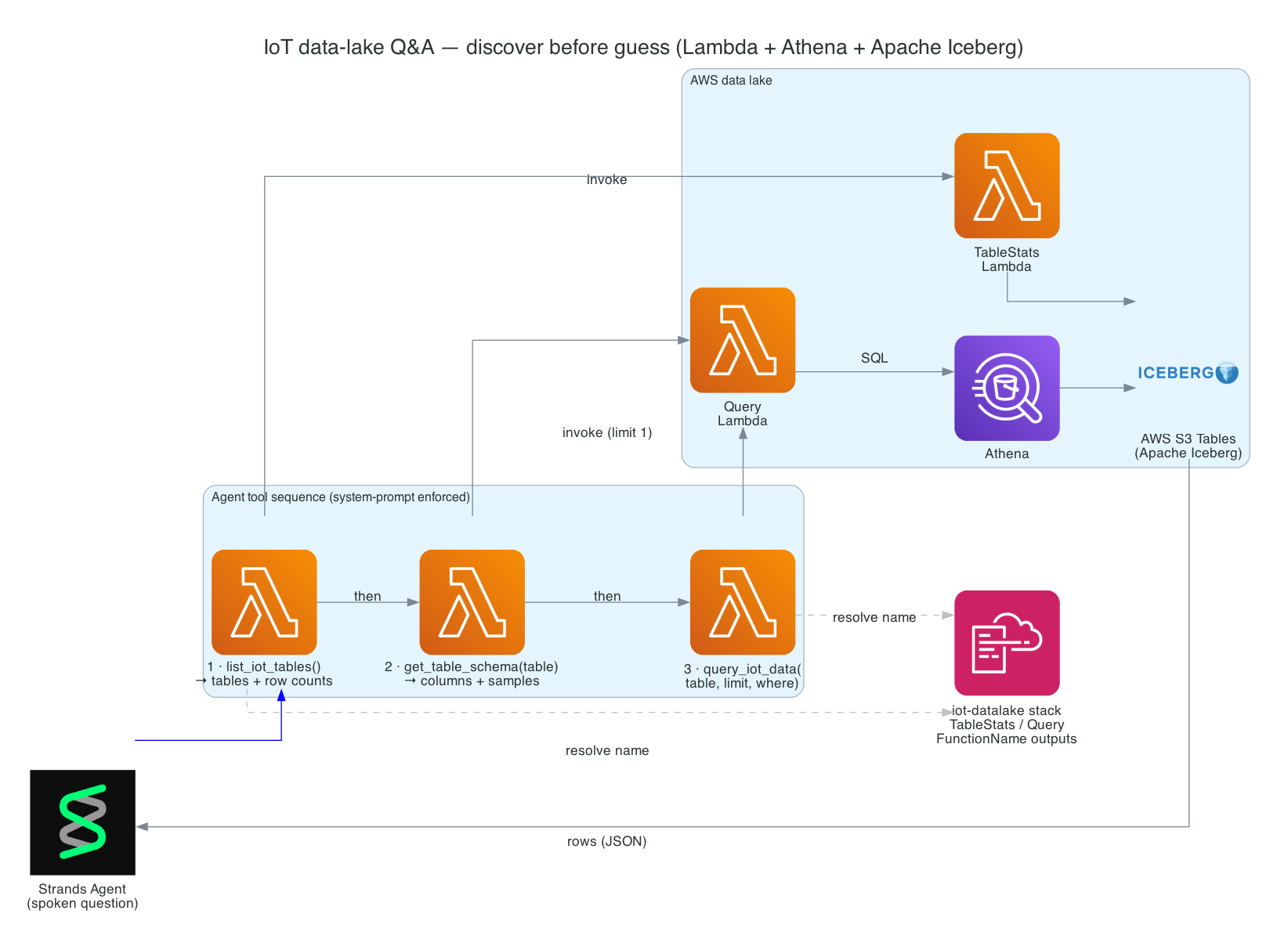
This is Part 6 of the series. So far the robot can move, see, and run the full per-wake loop. Now I want it to answer questions about real data — "Hey Reachy, has the kitchen water sensor tripped today?" — by querying an AWS data lake of IoT sensor readings, and speaking the answer back in one sentence.
This is Part 2 of a 3-part series covering a real-time voice-to-sign-language translation system. In Part 1, I covered the React frontend that captures speech, processes it with Amazon Nova 2 Sonic, and publishes cleaned sentence text via MQTT. But there is a missing piece — how does the frontend know what the physical hand is actually doing?
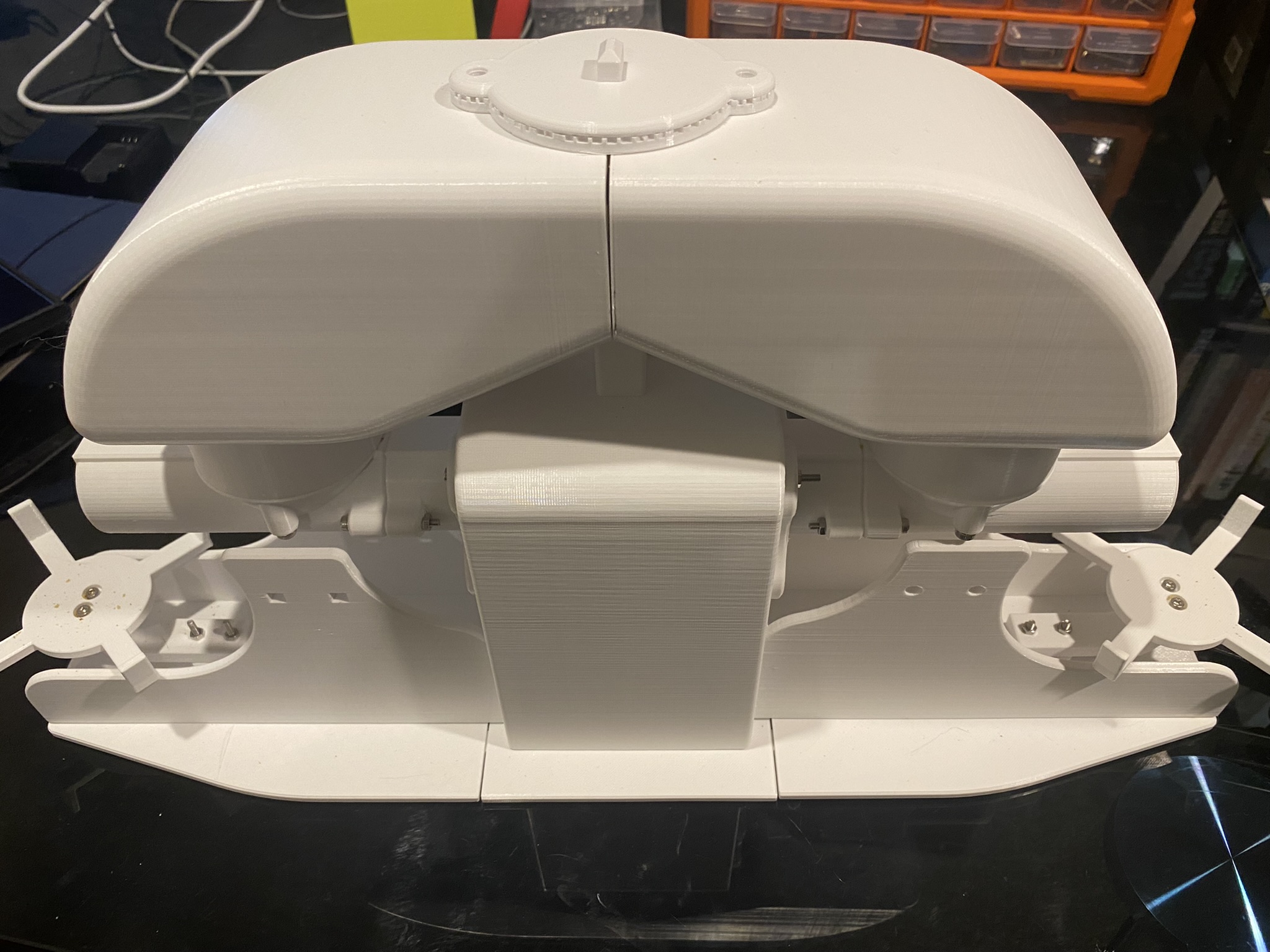
The answer is this repository: a small but critical AWS CDK stack that acts as the bridge between the edge device and the React frontend. It routes real-time hand state data from IoT Core to AppSync, enabling the frontend to receive live updates via GraphQL subscriptions — so the 3D hand animation stays synchronised with the physical Amazing Hand — an open-source robotic hand designed by Pollen Robotics and manufactured by Seeed Studio.
This post (Part 2) - Cloud Infrastructure (cdk-iot-amazing-hand-streaming) — AWS CDK stack that routes IoT Core messages through Lambda to AppSync for real-time GraphQL subscriptions
Part 3 - Edge AI Agent (strands-agents-amazing-hands) — Strands Agent powered by Amazon Nova 2 Lite on NVIDIA Jetson that translates sentence text to ASL servo commands, drives the Amazing Hand, and publishes state back
Goals
Route real-time hand state data from IoT Core MQTT to AppSync using an IoT Rules Engine SQL query and Lambda
Flatten nested MQTT finger angle payloads into a flat GraphQL schema for the createHandState mutation
Enable the React frontend to receive live hand state updates via AppSync onCreateHandState GraphQL subscriptions
Extract the device name dynamically from the MQTT topic path using topic(3) in the IoT Rule SQL
Define all infrastructure as code using AWS CDK in TypeScript
Integrate with the existing Amplify Gen 2 managed AppSync API and DynamoDB table from Part 1
The Overall System
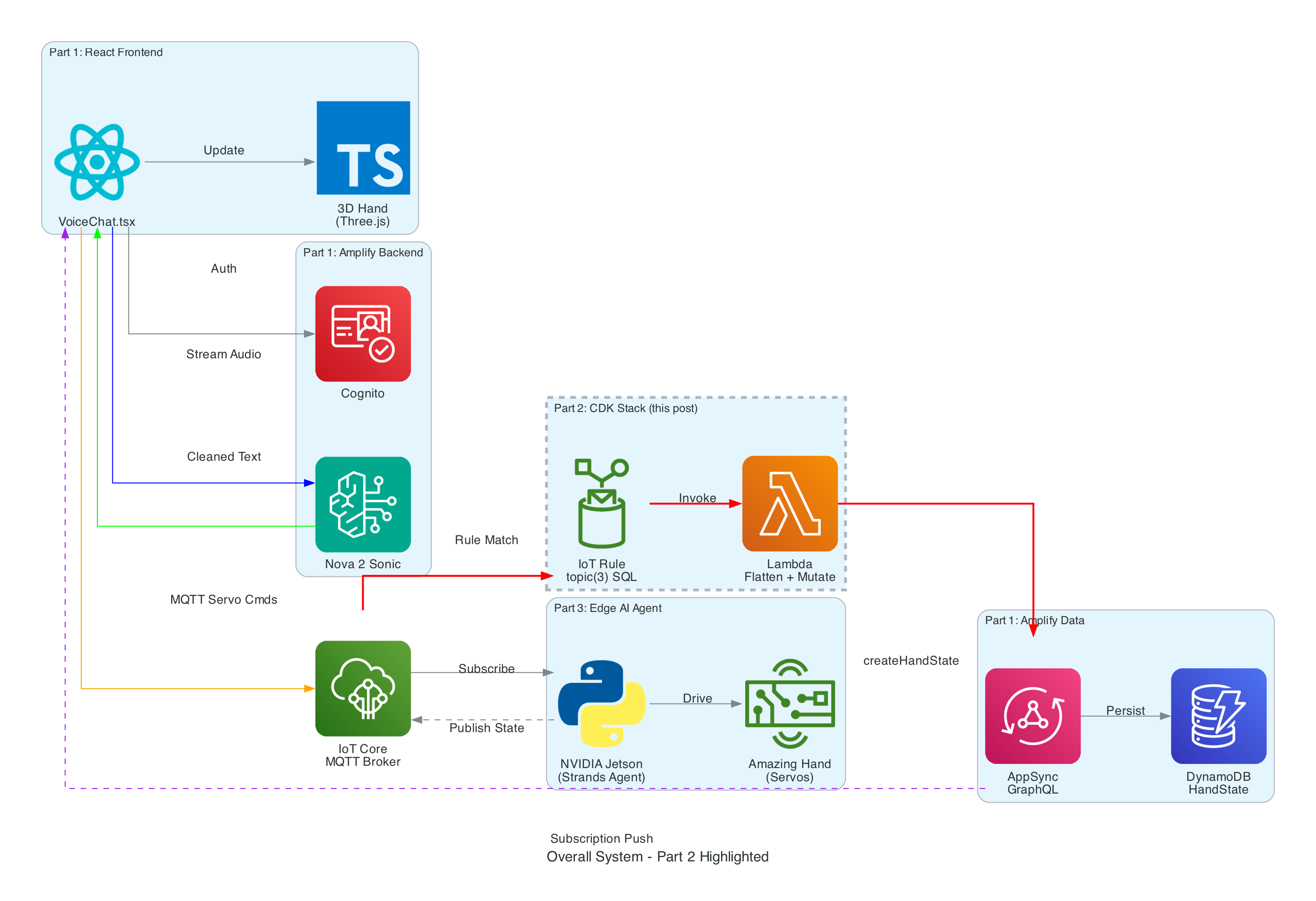
This diagram shows the complete end-to-end system. Part 2 is the infrastructure highlighted in the middle — the IoT Rule, Lambda, and AppSync connection that enables real-time state feedback from the edge device back to the frontend.
How Part 2 fits in:
Part 1 (Frontend) publishes cleaned sentence text to the-project/robotic-hand/{deviceName}/action and subscribes to AppSync onCreateHandState for live updates
Part 3 (Edge Device) receives sentence text, translates it to ASL servo commands via the Strands Agent powered by Amazon Nova 2 Lite, drives the Amazing Hand, and publishes state back to the-project/robotic-hand/{deviceName}/state
Part 2 (This stack) listens on the /state topic, transforms the payload, and pushes it into AppSync — completing the real-time feedback loop
Architecture
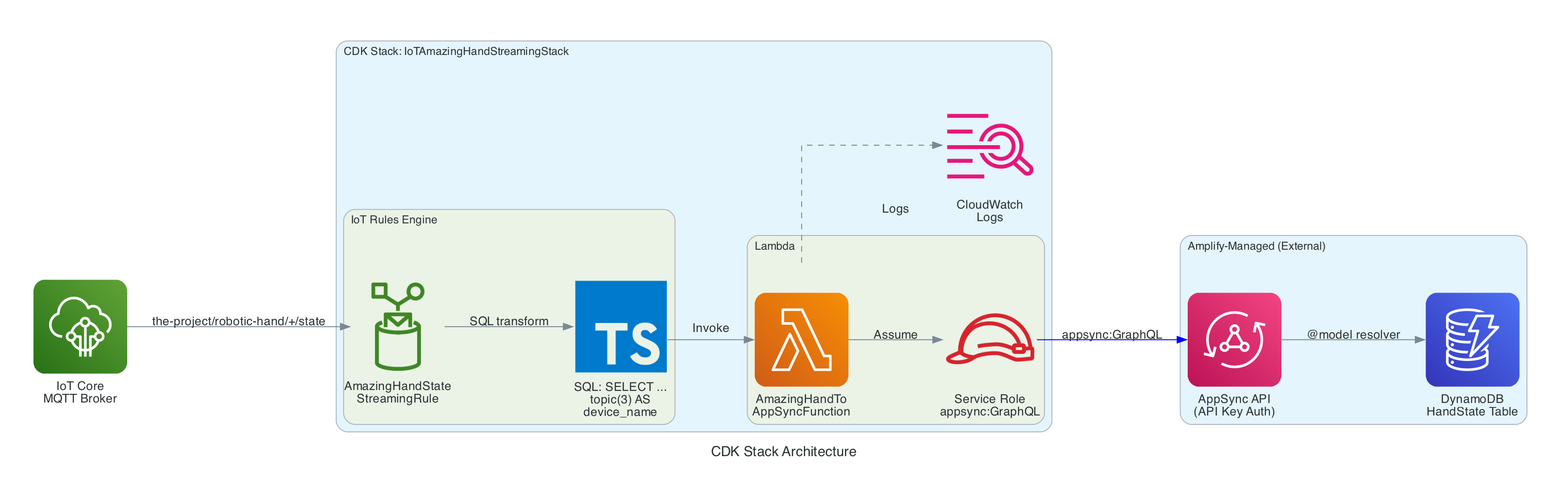
The stack is intentionally small — a single IoT Rule, a single Lambda function, and the IAM glue to connect them. The AppSync API and DynamoDB table are managed by the Amplify Gen 2 backend in Part 1, so this stack only needs to call the existing createHandState mutation.
IoT Topic Rule (AmazingHandStateStreamingRule) — Matches MQTT messages on the-project/robotic-hand/+/state using SQL SELECT gesture, letter, ts, fingers, video_url, topic(3) AS device_name, then invokes the Lambda function
Lambda Function (AmazingHandToAppSyncFunction) — Node.js 18 function that receives the IoT event, flattens the nested fingers object into individual angle fields, and calls the AppSync createHandState GraphQL mutation using the Amplify v6 SDK with API Key authentication
Lambda IAM Role — Service role with AWSLambdaBasicExecutionRole for CloudWatch Logs and an inline policy granting appsync:GraphQL on the AppSync API
Lambda Permission — Allows the IoT service (iot.amazonaws.com) to invoke the Lambda function
Resources managed externally (by Amplify Gen 2 in Part 1):
AppSync API — GraphQL API with HandState model, createHandState mutation, and onCreateHandState subscription
DynamoDB Table — HandState table with auto-generated resolvers from the @model directive
The IoT Rule is the entry point. It listens on the MQTT topic pattern the-project/robotic-hand/+/state where + is a single-level wildcard matching any device name (e.g. XIAOAmazingHandRight).
The SQL query (using AWS IoT SQL version 2016-03-23) selects specific fields from the MQTT payload and enriches them with metadata extracted from the topic path:
The fingers object uses a nested structure with angle_1 and angle_2 per finger — representing the two joints of each finger on the Amazing Hand. This nested format is natural for the edge device to produce but needs to be flattened for the GraphQL schema.
The Lambda calls this mutation to persist the hand state and trigger the real-time subscription:
mutationCreateHandState($input:CreateHandStateInput!){ createHandState(input:$input){ id deviceName gesture letter indexAngle1 indexAngle2 middleAngle1 middleAngle2 ringAngle1 ringAngle2 thumbAngle1 thumbAngle2 timestamp videoUrl createdAt } }
When AppSync receives this mutation, two things happen:
The hand state record is persisted to DynamoDB via the auto-generated @model resolver
The onCreateHandStatesubscription is triggered, pushing the new record to all subscribed clients — including the React frontend from Part 1, which uses this data to update the 3D hand animation, signed letter history, and video feed in real-time
The entire stack is defined in approximately 74 lines of TypeScript. The stack accepts the AppSync API URL, API key, and API ID as props, which are injected via environment variables during deployment:
The stack creates the Lambda function with the AppSync connection details as environment variables, grants it appsync:GraphQL permissions scoped to the specific API, creates the IoT Topic Rule with the SQL query, and grants IoT permission to invoke the Lambda.
Two stack outputs are exported for reference:
AmazingHandIoTRuleArn — The IoT Rule ARN
AmazingHandLambdaFunctionArn — The Lambda function ARN
The project includes a GitHub Actions workflow (.github/workflows/aws-cdk-deploy.yml) that automates deployment:
Triggers on pushes to main and dev branches
Authenticates using OIDC (no static AWS credentials stored in GitHub)
Automatically discovers the AppSync configuration by:
Reading the Amplify App ID from SSM Parameter Store (/iot/amplify/amazinghand)
Finding the Amplify data CloudFormation stack
Extracting the AppSync API ID from CloudFormation stack resources, then querying the AppSync API directly for the URL and API key
Runs cdk deploy with the discovered values
This means the stack automatically stays connected to the correct AppSync API without manual configuration.
Technical Challenges & Solutions
Challenge 1: Flattening Nested IoT Payloads for GraphQL
Problem: The edge device publishes finger angles in a nested JSON structure (fingers.index.angle_1), but the AppSync GraphQL schema uses flat fields (indexAngle1). The IoT Rules Engine SQL can select nested objects but cannot rename nested fields into flat ones.
Solution: The Lambda function handles the transformation. It receives the nested fingers object from the IoT Rule and manually flattens each field with safe defaults (0 for missing angles, null for optional fields). This keeps the IoT Rule SQL simple and the edge device payload natural.
Challenge 2: Connecting to Amplify-Managed AppSync
Problem: The AppSync API is managed by Amplify Gen 2 in Part 1's repository, not by this CDK stack. The API URL, API key, and API ID change between environments and deployments.
Solution: The CI/CD pipeline automatically discovers the AppSync configuration at deploy time by reading from SSM Parameter Store and CloudFormation stack outputs. For local development, the values are passed via environment variables in deploy.sh. The CDK stack accepts them as typed props, keeping the infrastructure code clean.
Challenge 3: Extracting Device Name from MQTT Topic
Problem: The device name is part of the MQTT topic path (the-project/robotic-hand/XIAOAmazingHandRight/state), not the message payload. The Lambda needs it to set the deviceName field in the GraphQL mutation.
Solution: The IoT Rules Engine SQL function topic(3) extracts the 3rd segment of the topic path and aliases it as device_name. This is passed to the Lambda as part of the event, so the Lambda does not need to parse the topic itself. The wildcard + in the topic filter means this works for any device name without configuration changes.
git clone https://github.com/chiwaichan/cdk-iot-amazing-hand-streaming.git cd cdk-iot-amazing-hand-streaming npminstall cd lambda/amazing-hand-to-appsync &&npminstall&&cd../..
Deploy:
./deploy.sh
This bootstraps CDK (if needed) and deploys the stack with the AppSync configuration.
What's Next
In Part 3, I will cover the edge AI agent (strands-agents-amazing-hands) — a Strands Agent powered by Amazon Nova 2 Lite running on an NVIDIA Jetson that subscribes to the MQTT sentence text published by the frontend in Part 1, translates them into physical servo movements on the Pollen Robotics Amazing Hand for ASL fingerspelling, records video, and publishes hand state back to IoT Core — which this Part 2 stack routes through to AppSync for the frontend to consume.
Summary
This post covered the cloud infrastructure layer of the voice-to-sign-language translation system:
IoT Rules Engine listens on the-project/robotic-hand/+/state and extracts device name from the topic path using topic(3)
Lambda function flattens nested finger angle payloads (fingers.index.angle_1 → indexAngle1) and calls the AppSync createHandState GraphQL mutation
AppSync persists to DynamoDB and broadcasts onCreateHandState subscriptions to connected React clients in real-time
CDK stack is intentionally small (~74 lines) — it creates only the IoT Rule, Lambda, and IAM glue, relying on the Amplify-managed AppSync API from Part 1
CI/CD pipeline automatically discovers AppSync configuration from SSM Parameter Store, CloudFormation stack resources, and direct AppSync API calls — no manual configuration needed
The stack completes the real-time feedback loop: edge device publishes state → IoT Core → Lambda → AppSync → React frontend updates 3D hand animation
I've always wanted to dip my toes into building IoT solutions beyond doing what a typical tutorial teaches in only turning on LEDs - I wanted to build something that would used everyday. Plus, I often forget to feed the cats while I am away from home (for the day), so it would be nice to come home to a non-grumpy cat by feeding them remotely any time and from any where in the world using the internet.
To simply describe what is built, the Feeder uses an Iot button click to trigger events over the internet to instruct the feeder to dispense food into one or both food bowls.
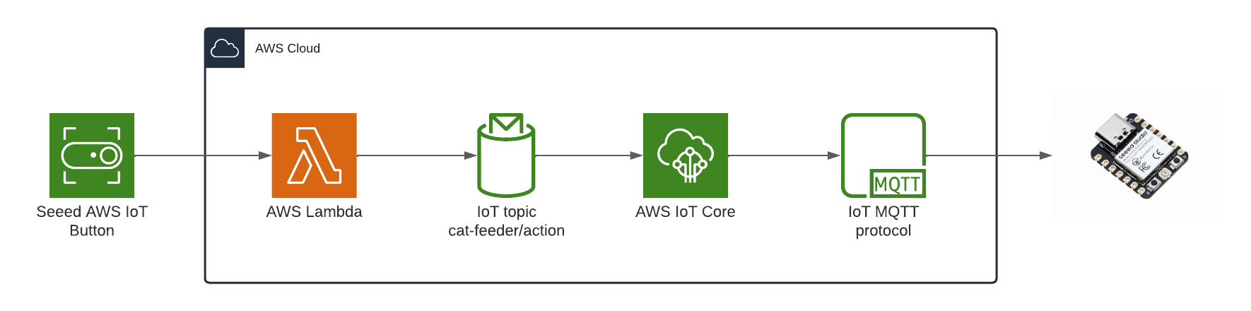
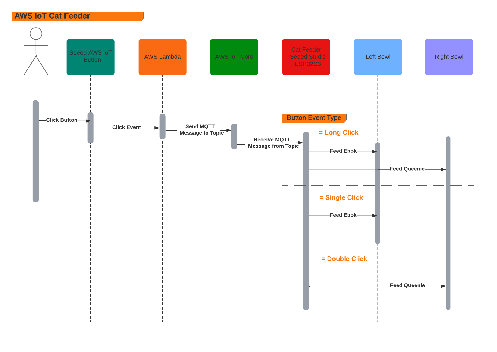
Here are some diagrams describing the architecture of the solution - the technical things that happens in-between the IoT button and the Cat Feeder.
When the Feeder receives a MQTT message from the AWS IoT Core Service, it runs the motor for 10 seconds to dispense food into either one of food bowls, and if the message contains an event value to dispense food into both bowls we can run both motors concurrently using the L298N controller.
Here's a video of some timelapse picture captured during the 3 weeks it took to 3D print the feeder.
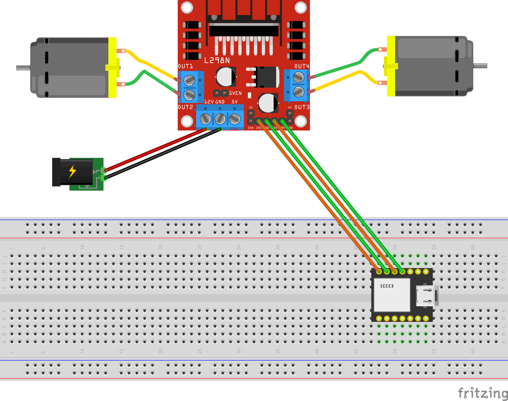
The Feeder is made up of a small handful of basic hardware components, below is a Breadboard diagram depicting the components used and how they are all wired up together. A regular 12V 2A DC power adapter supply is used to power all the components.
The code to start and stop a motor is about 10 lines of code as shown below. This is the completed version of the Arduino Sketch shown in Part 2 of this blog series when it was partially written at the time.
#include "secrets.h"
#include <WiFiClientSecure.h>
#include <MQTTClient.h>
#include <ArduinoJson.h>
#include "WiFi.h"

// The MQTT topics that this device should publish/subscribe
#define AWS_IOT_PUBLISH_TOPIC   "cat-feeder/states"
#define AWS_IOT_SUBSCRIBE_TOPIC "cat-feeder/action"

WiFiClientSecure net = WiFiClientSecure();
MQTTClient client = MQTTClient(256);

int motor1pin1 = 32;
int motor1pin2 = 33;
int motor2pin1 = 16;
int motor2pin2 = 17;

void connectAWS()
{
  WiFi.mode(WIFI_STA);
  WiFi.begin(WIFI_SSID, WIFI_PASSWORD);

  Serial.println("Connecting to Wi-Fi");
  Serial.println(AWS_IOT_ENDPOINT);

  while (WiFi.status() != WL_CONNECTED) {
    delay(500);
    Serial.print(".");
  }

  // Configure WiFiClientSecure to use the AWS IoT device credentials
  net.setCACert(AWS_CERT_CA);
  net.setCertificate(AWS_CERT_CRT);
  net.setPrivateKey(AWS_CERT_PRIVATE);

  // Connect to the MQTT broker on the AWS endpoint we defined earlier
  client.begin(AWS_IOT_ENDPOINT, 8883, net);

  // Create a message handler
  client.onMessage(messageHandler);

  Serial.println("Connecting to AWS IOT");
  Serial.println(THINGNAME);

  while (!client.connect(THINGNAME)) {
    Serial.print(".");
    delay(100);
  }

  if (!client.connected()) {
    Serial.println("AWS IoT Timeout!");
    return;
  }

  Serial.println("About to subscribe");
  // Subscribe to a topic
  client.subscribe(AWS_IOT_SUBSCRIBE_TOPIC);

  Serial.println("AWS IoT Connected!");
}

void publishMessage()
{
  StaticJsonDocument<200> doc;
  doc["time"] = millis();
  doc["state_1"] = millis();
  doc["state_2"] = 2 * millis();
  char jsonBuffer[512];
  serializeJson(doc, jsonBuffer); // print to client

  client.publish(AWS_IOT_PUBLISH_TOPIC, jsonBuffer);

  Serial.println("publishMessage states to AWS IoT" );
}

void messageHandler(String &topic, String &payload) {
  Serial.println("incoming: " + topic + " - " + payload);

  StaticJsonDocument<200> doc;
  deserializeJson(doc, payload);
  const char* event = doc["event"];

  Serial.println(event);

  feedMe(event);
}

void setup() {
  Serial.begin(9600);
  connectAWS();

  pinMode(motor1pin1, OUTPUT);
  pinMode(motor1pin2, OUTPUT);
  pinMode(motor2pin1, OUTPUT);
  pinMode(motor2pin2, OUTPUT);
}

void feedMe(String event) {
  Serial.println(event);

  bool feedLeft = false;
  bool feedRight = false;

  if (event == "SINGLE") {
    feedLeft = true;
  }
  if (event == "DOUBLE") {
    feedRight = true;
  }
  if (event == "LONG") {
    feedLeft = true;
    feedRight = true;
  }

  if (feedLeft) {
    Serial.println("run left");
    digitalWrite(motor1pin1, HIGH);
    digitalWrite(motor1pin2, LOW);
  }

  if (feedRight) {
    Serial.println("run right");
    digitalWrite(motor2pin1, HIGH);
    digitalWrite(motor2pin2, LOW);
  }

  delay(10000);
  digitalWrite(motor1pin1, LOW);
  digitalWrite(motor1pin2, LOW);
  digitalWrite(motor2pin1, LOW);
  digitalWrite(motor2pin2, LOW);
  delay(2000);

  Serial.println("fed");
}

void loop() {
  publishMessage();
  client.loop();
  delay(3000);
}
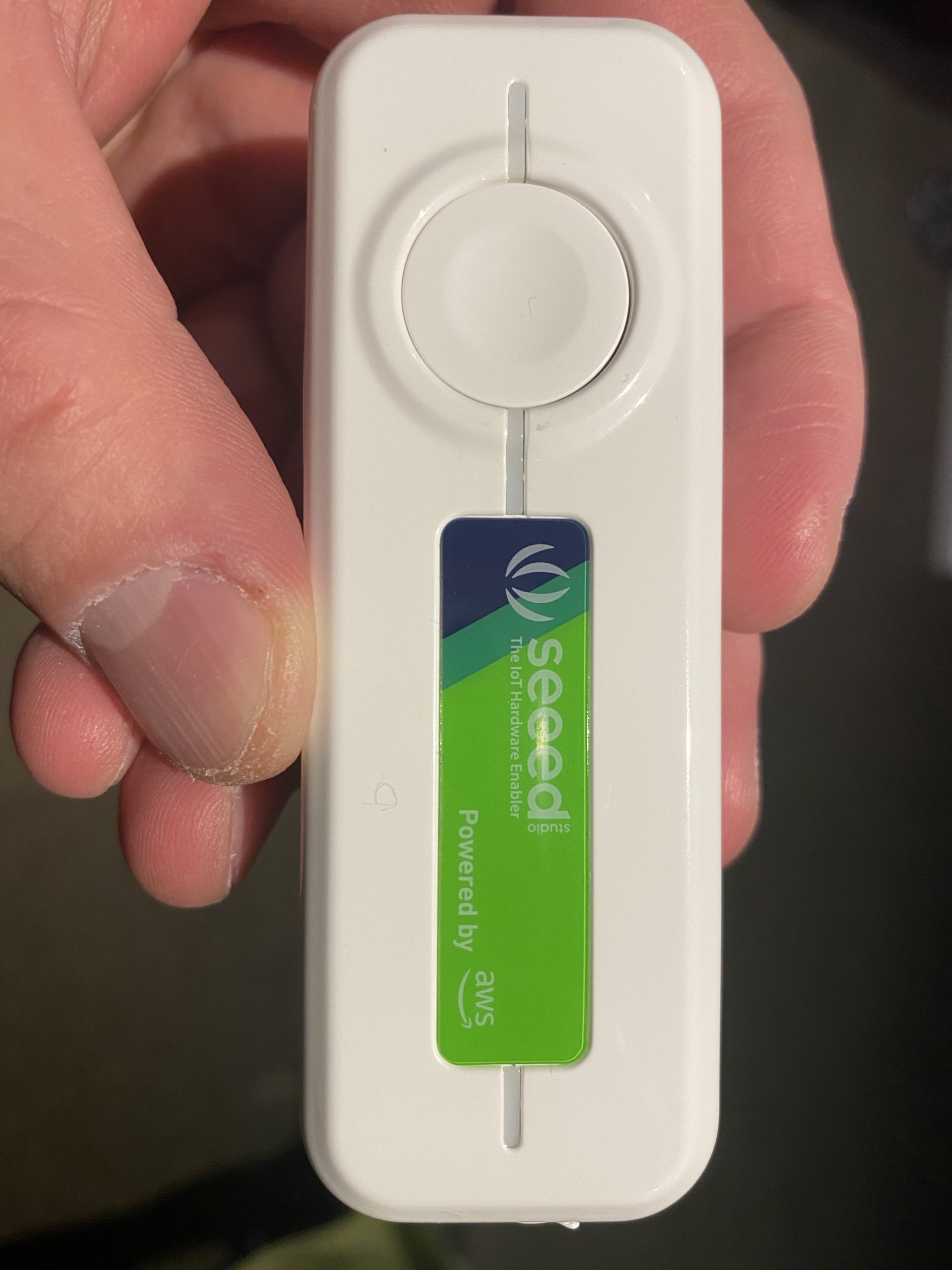
The Seeed AWS IoT Button is able to detect 3 different types of click events: Long, Single and Double, and we are able to leverage this all the way to the feeder so we will have it performing certains actions base on the click event type.
The video below demonstrates the following scenarios:
Long Click: this will dispense food into both cat bowls
Single Click: this will dispense food into Ebok's cat bowl
Double Click: this will dispense food into Queenie's cat bowl
Build the nervous system of an ultimate nerd project I have in mind that would allow me to voice control actions controlling servos, LEDs and audio outputs, by using a mesh of Seeed XIAO BLE Sense micro-controllers and TinyML Machine Learning.
If you are forgetful when it comes to feeding your fur babies like me, and you often only realise you need to put some dry food into the bowl when you are at work then you should read these series of blogs. Over time, I'll be designing and building a smart cat feeder over time using a combination of components such as Arduino micro controllers, motors, sensors and IoT devices and Cloud services. I'll publish the steps taken in these series of blogs, also, I'll publish any designs and source code as I figure things out and make decisions on aspects of the design.
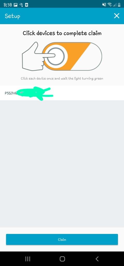
In this part 1 of the series, I will do a walkthrough on setting up an AWS IoT 1-Click device to trigger a Lambda Function. I got myself one of these Seeed IoT buttons for $20; I also bought a NCR18650B battery which I realised later on is only required if I wanted to run the device without it being powered by a USB type-C cable (used for charging the power as well).
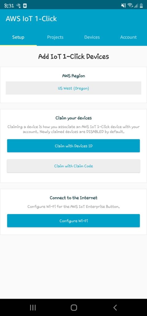
Firstly, make sure you have an AWS account. Then install the AWS IoT1-Click app onto your phone and log in using your AWS account. With these we will be able to link IoT devices up to our AWS account.
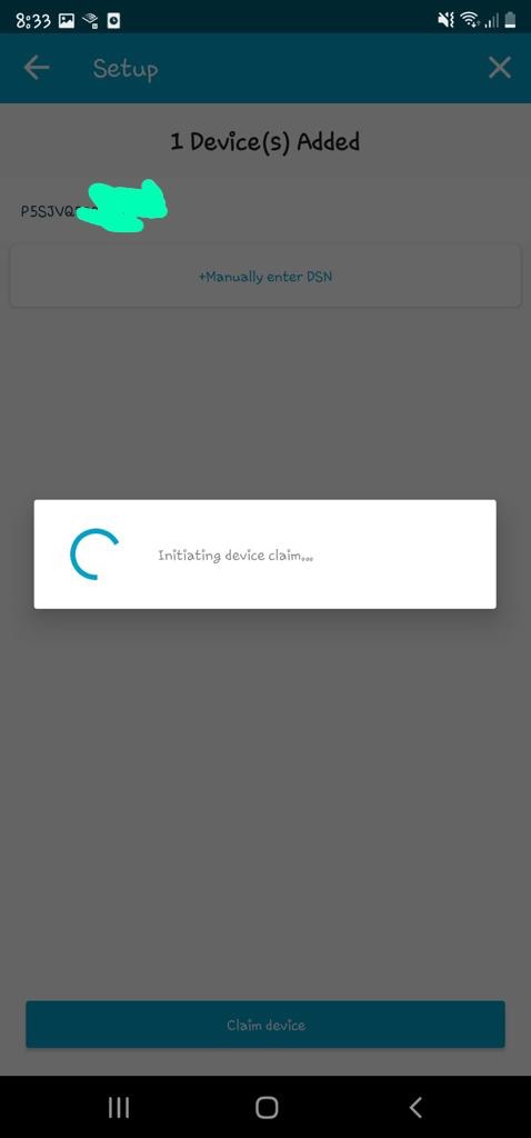
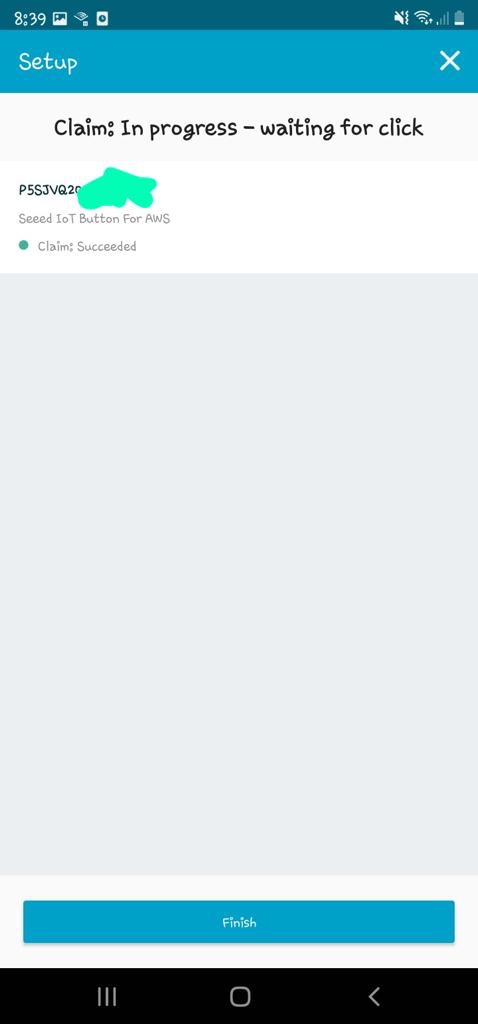
Claim the IoT device with Device ID
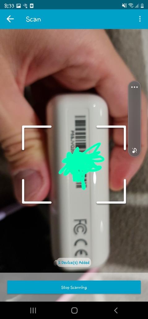
Scan the barcode on the back of the device; you can scan multiple devices in bulk.
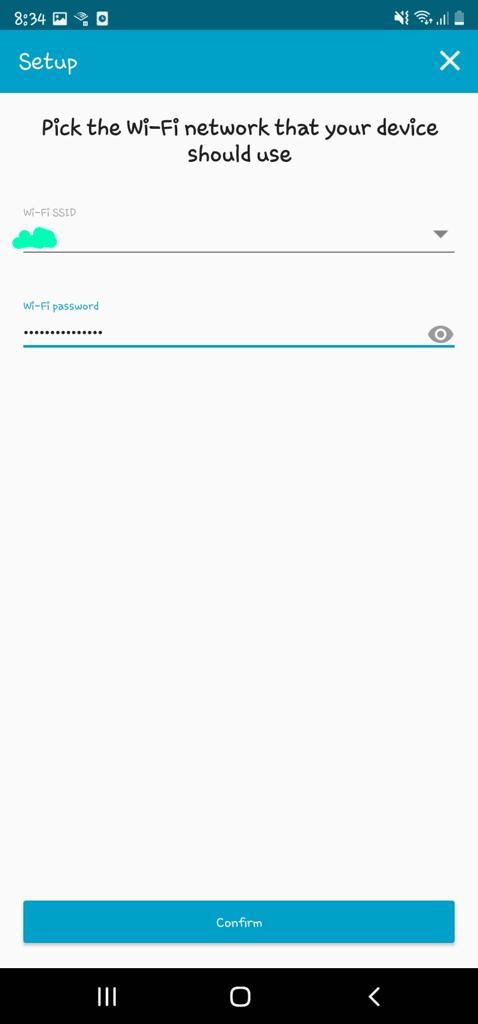
Next, I'll set up the Wifi on the device so that it can reach the internet internet from home. Can't see why I can't set it up to my phone's AP for feeding on the go, I'll try it out some other time.
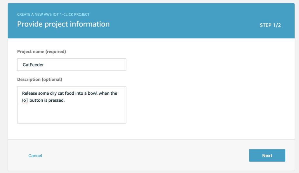
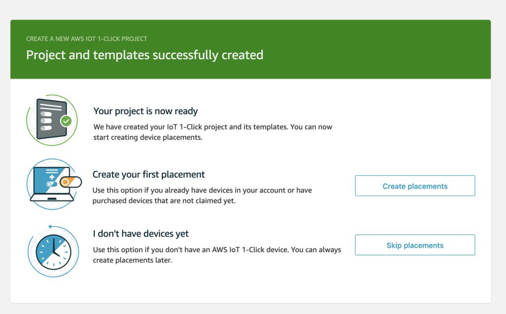
Now we'll create a project and add the IoT device to a placement group in the AWS Console. Give a name and description for the project.
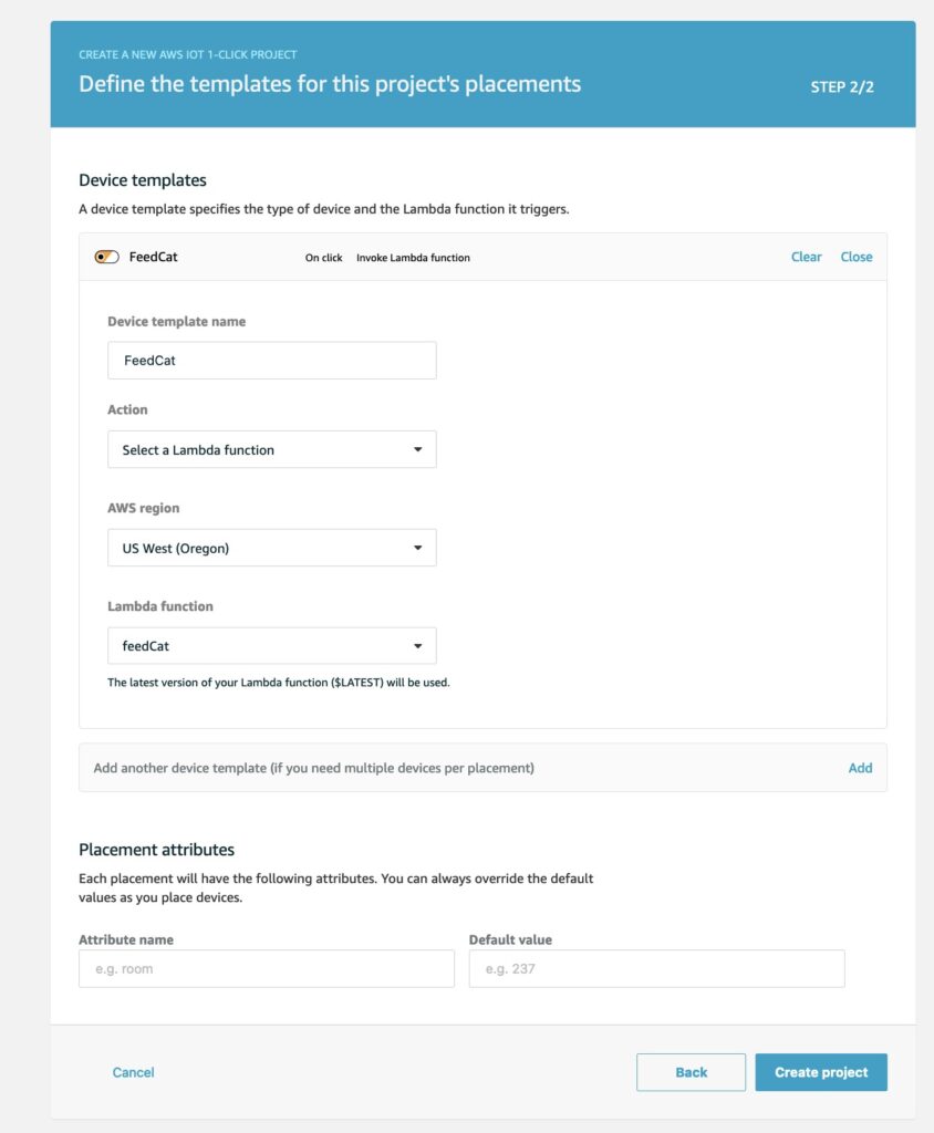
Next define a template, this is where we create a Lambda function; all the plumbing between the IoT device and Lambda will be handled for us.
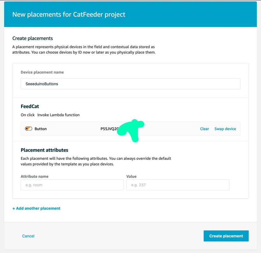
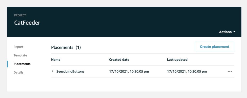
Next we create a placement for the Iot device.
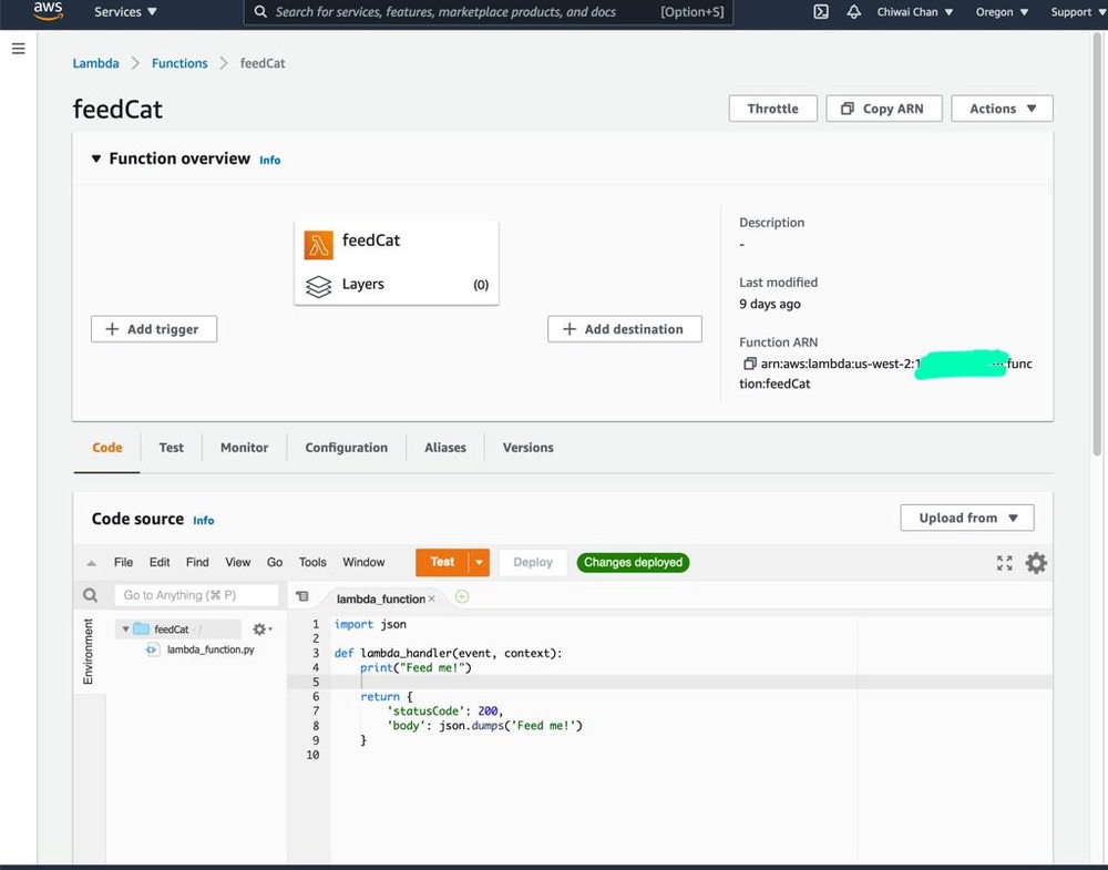
Since I have no Arduino micro-controllers (have yet to buy one), I will get the Lambda to log a message.
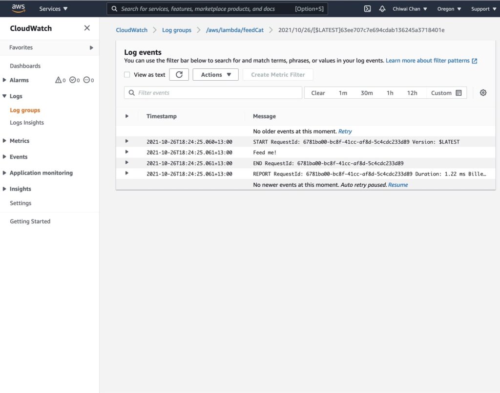
Push the button on the Iot device, wait for the event LED status to turn green after flashing white then check the logs CloudWatch Logs.
At some point I have to code the Lambda to perform a real action as each event comes through, which will be demonstrated in a following blog in the series instead of just logging to CloudWatch logs.
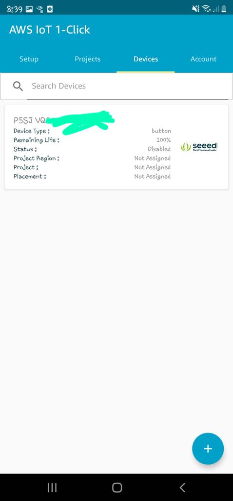
Within the app on your phone you can see status of each IoT device such as the remaining battery life percentage.
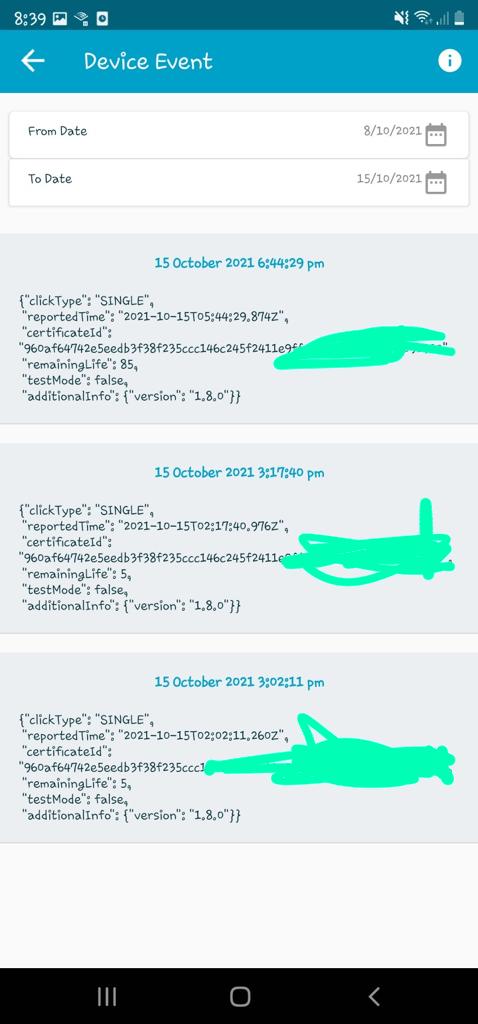
As well as a history of the button's events.
In the next blog, I'll configure the Lambda to push the event to a Topic for AWS IoT Core to subscribe to, which in turns will trigger an event to an ESP32 ( I've yet to decide on a specific version of the micro-controller) using the IoT MQTT protocol.