These are the slides from my talk at the AWS User Group Wellington meet-up on 26 May 2026, walking through how I built a real-time pipeline that listens to spoken commands in the browser and drives a Sphero RVR — exact distances, exact angles — with live telemetry streaming back into the UI.
Tip: click into the slides and use the arrow keys to navigate, or hit the fullscreen button for the best experience.
arduino-aws-iot — ESP32-S3 firmware. The talk focuses on the sphero_rvr device group, including the new maneuver executor (forward, reverse, turn, cancel) layered on top of the existing drive D-pad.
cdk-iot-sphero-rvr-streaming — AWS CDK stack that filters the RVR telemetry MQTT topic, flattens the nested payload in Lambda, and forwards it as a GraphQL mutation to an Amplify-managed AppSync API.
amplify-react-nova-sonic-voice-chat-sphero-rvr — React + AWS Amplify Gen 2 frontend. The same Cognito identity is used for Bedrock streaming, IoT publish, and the AppSync subscription that surfaces live telemetry.
Big thanks to the AWS User Group Wellington organisers and everyone who came along — happy to chat about any of the code, the maneuver framework, or where the project goes next.
These are the slides from my talk at the AWS User Group Wellington meet-up on 29 April 2026, walking through how I built a real-time pipeline that listens to speech in the browser and drives a robotic hand to fingerspell the words in American Sign Language (ASL).
Tip: click into the slides and use the arrow keys to navigate, or hit the fullscreen button for the best experience.
This is Part 3 of a 3-part series covering a real-time voice-to-sign-language translation system. In Part 1, I covered the React frontend that captures speech, processes it with Amazon Nova 2 Sonic, and publishes cleaned sentence text via MQTT. In Part 2, I covered the AWS CDK stack that routes IoT Core messages through Lambda to AppSync for real-time GraphQL subscriptions.
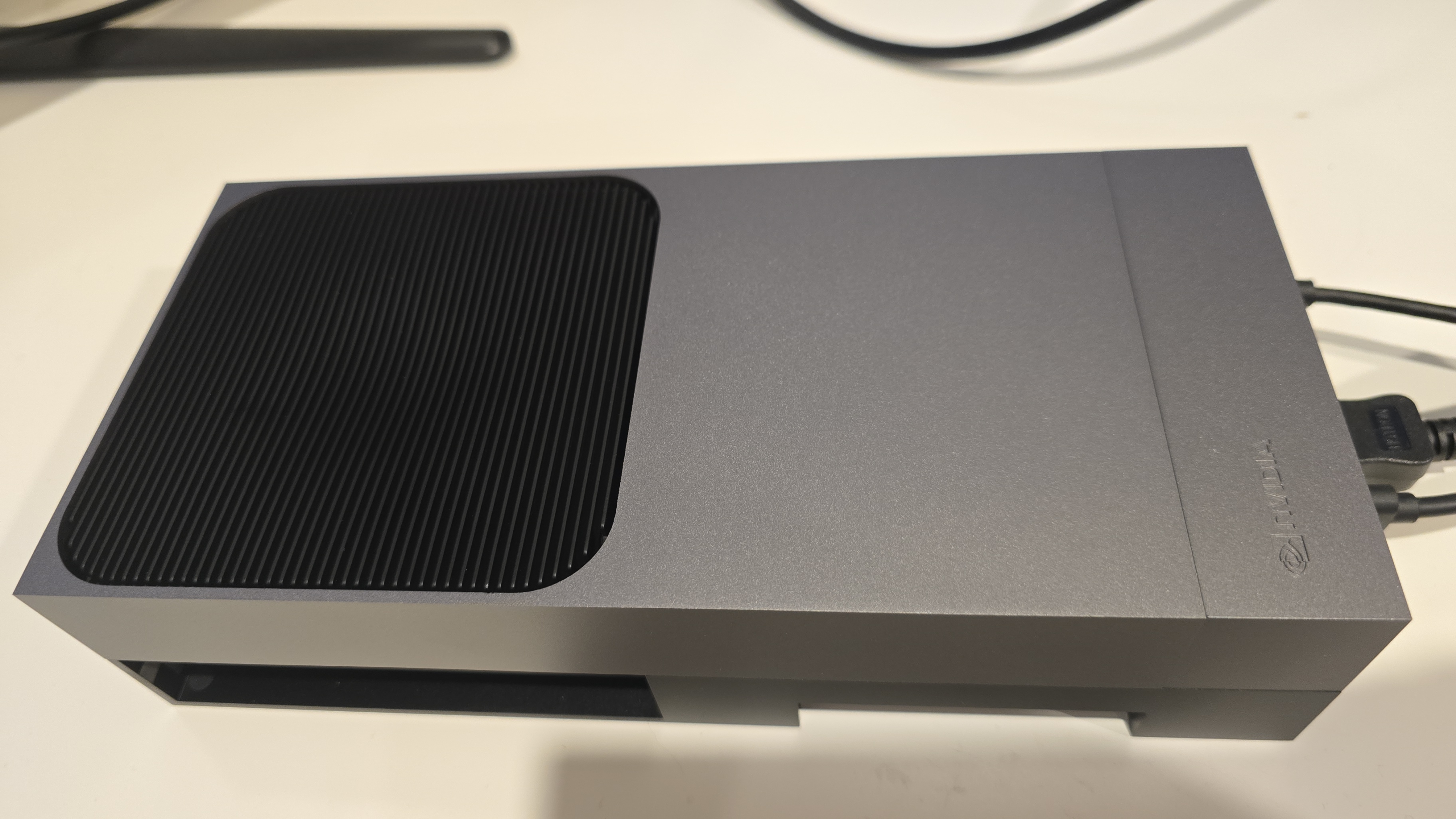
This post covers the final piece — the edge AI agent that actually makes the physical hand move. It is a Strands Agent running on an NVIDIA Jetson that subscribes to MQTT commands from the frontend, uses Amazon Nova 2 Lite to invoke the fingerspell tool, drives the Pollen Robotics Amazing Hand's Feetech SCS0009 servos for ASL fingerspelling letter by letter, records video of the hand in action, uploads it to S3, and publishes hand state back to IoT Core — which Part 2's infrastructure routes through to the frontend via AppSync.
This post (Part 3) - Edge AI Agent (strands-agents-amazing-hands) — Strands Agent powered by Amazon Nova 2 Lite on NVIDIA Jetson that translates sentence text to ASL servo commands, drives the Amazing Hand, and publishes state back
Goals
Receive MQTT commands from the React frontend (plain text or JSON with sentence field) and drive the Amazing Hand servos for ASL fingerspelling
Use the Strands Agents framework with Amazon Nova 2 Lite (us.amazon.nova-2-lite-v1:0) to invoke the fingerspell tool — the LLM passes the incoming text verbatim to the tool for letter-by-letter ASL spelling
Fingerspell text using the 26-letter ASL alphabet (A-Z), with each letter held for 0.8 seconds and spaces adding a 0.4-second pause
Control 8 Feetech SCS0009 servos (4 fingers x 2 joints) on the Pollen Robotics Amazing Hand via serial bus at 1M baud using the rustypot library
Record video of the hand via OpenCV during each fingerspelling sequence, encode to H.264 MP4 via imageio-ffmpeg, upload to S3, and include a presigned URL in the state message
Publish real-time hand state (servo angles, letter, video URL) to IoT Core over MQTT — which Part 2's CDK stack routes to AppSync for the frontend to consume
Authenticate to AWS IoT Core using mTLS with X.509 device certificates
Create a fresh agent instance per MQTT message to prevent conversation history accumulation and unbounded token growth
Handle graceful shutdown with servo torque disable on SIGINT/SIGTERM
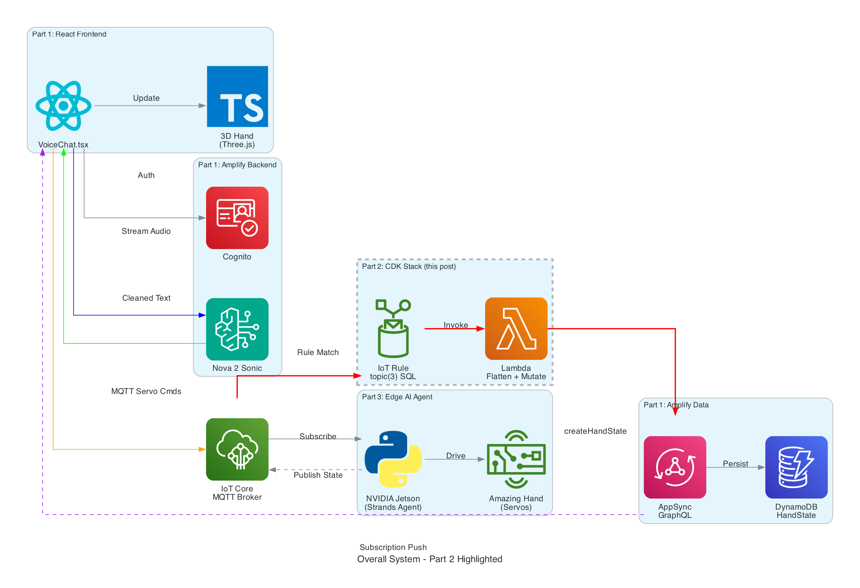
The Overall System
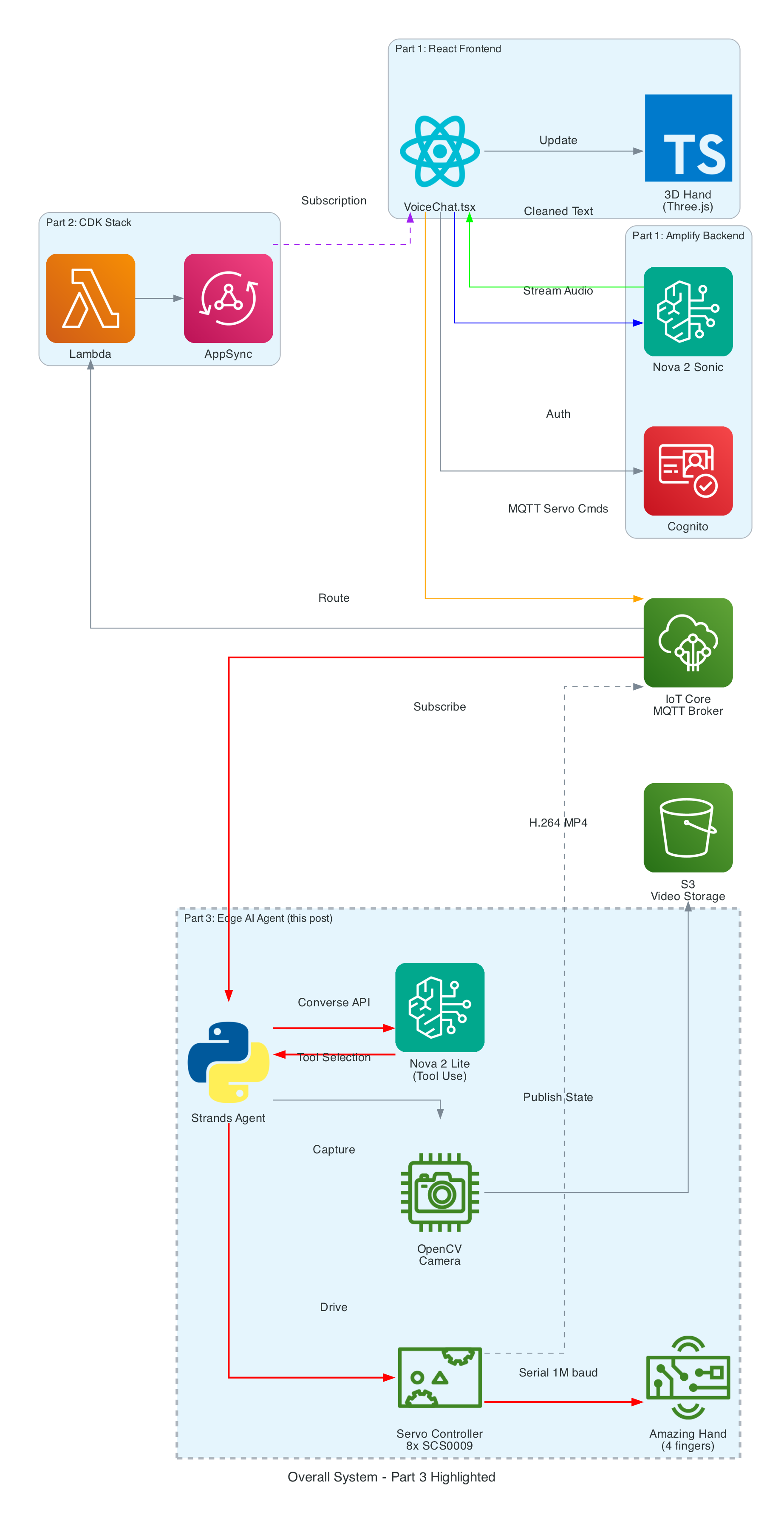
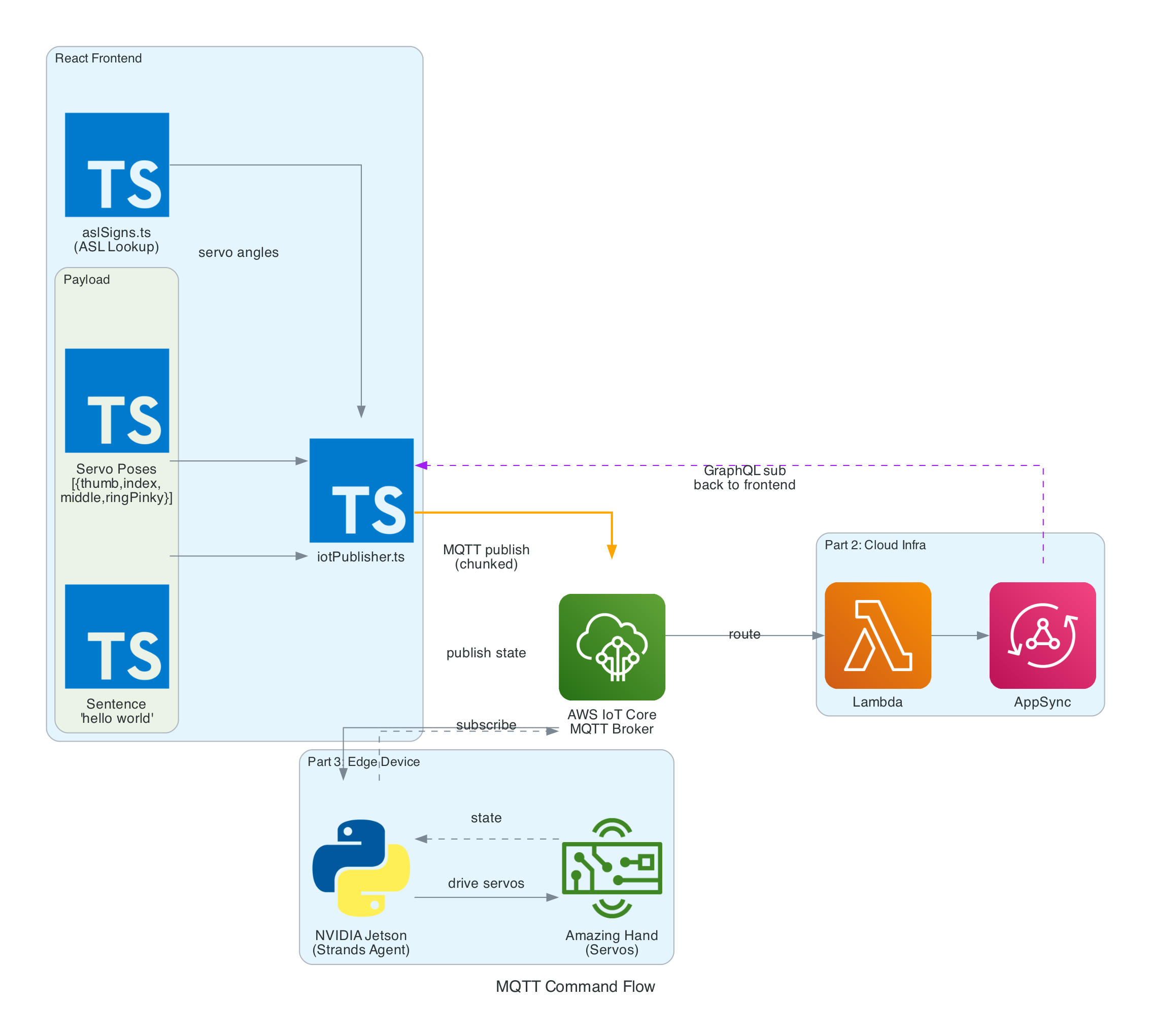
This diagram shows the complete end-to-end system. Part 3 is the edge device highlighted on the right — the NVIDIA Jetson running the Strands Agent that controls the Amazing Hand.
How Part 3 fits in:
Part 1 (Frontend) publishes cleaned sentence text to the-project/robotic-hand/{deviceName}/action via MQTT
Part 3 (This agent) subscribes to the /action topic, processes the command through the Strands Agent, drives the servos, records video, and publishes state back to /state
Part 2 (Infrastructure) picks up the /state messages and routes them through Lambda to AppSync, where the frontend receives them via GraphQL subscriptions
Architecture
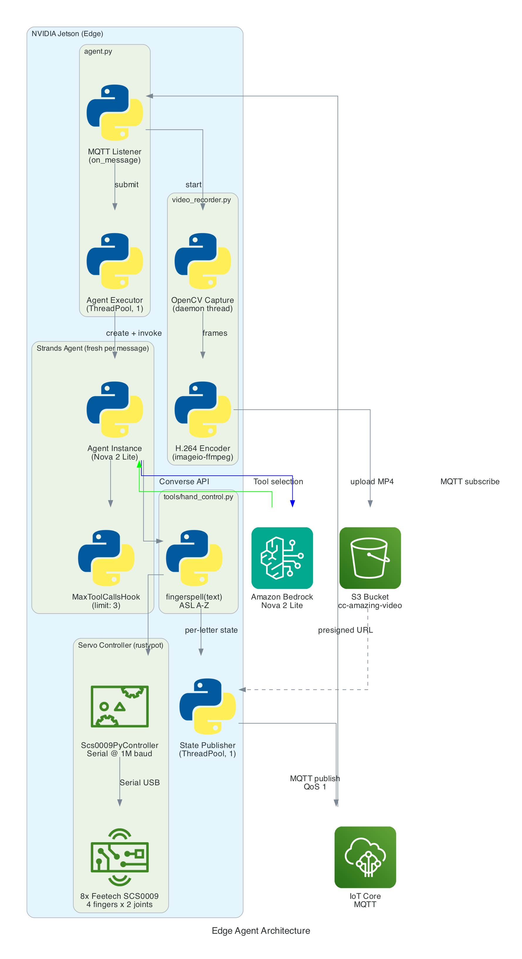
The agent is a Python application built on the Strands Agents framework. It runs as a long-lived MQTT listener on the NVIDIA Jetson, creating a fresh agent instance for each incoming message to keep memory bounded.
MQTT Listener (agent.py) — Subscribes to the action topic, parses incoming messages (plain text or JSON), and submits each action to a single-threaded agent executor to keep the AWS CRT MQTT event loop free
Strands Agent — A fresh Agent instance created per message with Amazon Nova 2 Lite as the model, the fingerspell tool as the available action, and a MaxToolCallsHook (limit 3) to prevent runaway tool-call loops
Fingerspell Tool (hand_control.py) — A @tool decorated function that the LLM invokes to spell text letter-by-letter using the 26-letter ASL alphabet
Servo Controller — Uses rustypot.Scs0009PyController to communicate with 8 Feetech SCS0009 servos over serial at 1M baud. Each finger has two servos controlled by dedicated move functions (Move_Index, Move_Middle, Move_Ring, Move_Thumb)
Video Recorder (video_recorder.py) — Background daemon thread captures frames via OpenCV, encodes to H.264 MP4 via imageio-ffmpeg, uploads to S3, and returns a presigned URL (1-hour expiry)
State Publisher — Non-blocking MQTT publisher on a separate thread that sends hand state (finger angles, letter, video URL) to the /state topic with QoS 1
The agent subscribes to an MQTT action topic (e.g. the-project/robotic-hand/XIAOAmazingHandRight/action) using mTLS authentication with X.509 device certificates. The first connection uses clean_session=True to flush any stale session state, then reconnects with clean_session=False for normal operation.
When a message arrives, the handler tries to parse it as JSON and extract the sentence field. If JSON parsing fails, it treats the entire payload as plain text. The action is then submitted to a single-threaded executor (agent_executor) to keep the AWS CRT MQTT event loop free:
The Strands Agents framework provides the core AI reasoning loop. A fresh agent instance is created for every MQTT message — this is deliberate to prevent conversation history from accumulating across messages, which would cause unbounded token growth over time.
The agent uses Amazon Nova 2 Lite (us.amazon.nova-2-lite-v1:0) via the Bedrock Converse API. Nova 2 Lite was chosen for its low-latency tool-use responses, which is critical for real-time servo control. The agent is configured with a MaxToolCallsHook that cancels tool calls beyond 3 to prevent infinite LLM tool-call loops.
The agent runs in fingerspell-only mode — only the fingerspell tool is available. The system prompt instructs the LLM to pass the entire message verbatim to the fingerspell tool without shortening or modifying it. State messages include a letter field identifying the current ASL letter being signed.
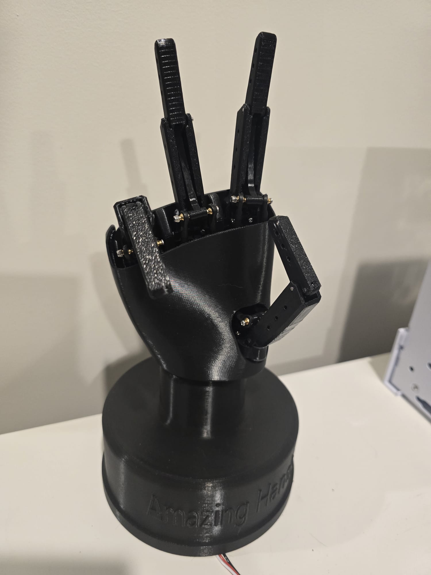
The Amazing Hand — an open-source robotic hand designed by Pollen Robotics and manufactured by Seeed Studio — has 4 fingers (index, middle, ring, thumb — no pinky) with 2 Feetech SCS0009 servos per finger (8 servos total) connected via a Waveshare driver board over serial USB at 1,000,000 baud.
Each servo has an angle range of -90 to +90 degrees. Per-servo calibration offsets (MiddlePos) are applied during move operations to account for physical alignment:
MiddlePos =[-17,8,-16,-4,-12,10,-9,9]
The control sequence for each finger:
Set goal speed for both servos (write_goal_speed) with a 0.2ms sleep between each speed write for serial bus timing
Convert angle to radians with calibration offset: np.deg2rad(MiddlePos[i] + angle)
Set goal position for both servos (write_goal_position)
5ms sleep after positions are set before the next finger's commands
The fingerspell(text) tool is decorated with @tool from the Strands framework, making it callable by the LLM during inference. It spells text letter-by-letter using the ASL alphabet. Each of the 26 letters (A-Z) is mapped to servo angle tuples for all 4 fingers. Each letter is held for 0.8 seconds, spaces add a 0.4-second pause, and non-letter characters are skipped. A state message with the current letter field is published after each letter.
Since the Amazing Hand has no pinky finger, ASL letters that require a pinky use the ring finger instead.
Video is recorded concurrently with each fingerspelling sequence:
Start recording — Before the agent is invoked, start_recording() launches a background daemon thread (video-capture) that captures frames from OpenCV VideoCapture(0) at the camera's native FPS (typically 30)
Stop and encode — After the agent completes, stop_recording_and_upload() stops the capture thread, converts frames from BGR (OpenCV) to RGB, and encodes to H.264 MP4 using imageio.v3 with the libx264 codec. The temp file is named hand_YYYYMMDD_HHMMSS_
Upload to S3 — The MP4 is uploaded to the configured S3 bucket (default: cc-amazing-video) with key videos/hand_YYYYMMDD_HHMMSS.mp4
Presigned URL — A presigned URL is generated with 1-hour expiry and appended to the last state message, which is re-published to the /state topic
After each servo movement, the tool publishes a state message to the MQTT /state topic (e.g. the-project/robotic-hand/XIAOAmazingHandRight/state) with QoS 1. Publishing is non-blocking — it submits to a dedicated _publish_executor thread to avoid blocking the servo tool.
The last published state is cached so that publish_state_with_video_url() can re-publish it with the presigned URL appended after video upload completes — without needing to re-read servo angles.
This state payload is what Part 2's CDK stack picks up via the IoT Rule, flattens in Lambda, and pushes into AppSync for the frontend to consume.
Problem: Strands Agents maintain conversation history by default. Over time, as hundreds of MQTT messages are processed, the token count grows unboundedly, increasing latency and cost.
Solution: A fresh Agent instance is created for every MQTT message. This discards all prior conversation history, keeping each invocation lightweight. Token usage (input, output, total) is logged after each invocation for monitoring.
Problem: The LLM might enter a loop of calling tools repeatedly — for example, calling fingerspell then deciding to call it again with modified text, then again.
Solution: A custom MaxToolCallsHook implementing the Strands HookProvider interface. It counts tool calls per agent invocation and cancels any tool call beyond the limit of 3. This is injected into the agent via hooks=[MaxToolCallsHook()].
Problem: The Pollen Robotics Amazing Hand has only 4 fingers (index, middle, ring, thumb) — no pinky. Several ASL letters require specific pinky positions (e.g. I, J, Y).
Solution: ASL letters that require a pinky use the ring finger instead. The 26-letter ASL alphabet is manually mapped to 4-finger servo angle tuples, approximating the correct hand shape with the available fingers.
Problem: Sending servo commands too quickly over the serial bus causes missed commands or erratic movement. The Feetech SCS0009 protocol requires time between operations.
Solution: A 0.2ms sleep is inserted between speed writes, and a 5ms sleep is added after both goal positions are set, giving the serial bus time to process each command before the next finger's sequence begins.
The agent will connect to IoT Core, subscribe to the action topic, and wait for commands. When a message arrives, it will process it through the Strands Agent, drive the servos, record video, and publish state back.
Summary
This post covered the edge AI agent — the final piece of the voice-to-sign-language translation system:
Strands Agents framework with Amazon Nova 2 Lite for tool-use — a fresh agent per MQTT message prevents history bloat, with MaxToolCallsHook limiting calls to 3
ASL fingerspelling with the 26-letter alphabet (A-Z), each letter held for 0.8 seconds — the fingerspell tool is decorated with @tool for LLM invocation
8 Feetech SCS0009 servos on 4 fingers controlled via rustypot over serial at 1M baud, with per-servo calibration offsets
Video pipeline captures via OpenCV in a background daemon thread, encodes to H.264 MP4 via imageio-ffmpeg, uploads to S3, and includes a 1-hour presigned URL in the final state message
Non-blocking threading with 2 thread pools (agent executor off MQTT event loop, state publisher) and a daemon thread for video capture
Real-time state publishing to IoT Core after every servo movement — which Part 2's CDK stack routes through Lambda to AppSync, completing the feedback loop to the React frontend in Part 1
Graceful shutdown disables servo torque on SIGINT/SIGTERM to release the servos and prevent power draw
This is Part 2 of a 3-part series covering a real-time voice-to-sign-language translation system. In Part 1, I covered the React frontend that captures speech, processes it with Amazon Nova 2 Sonic, and publishes cleaned sentence text via MQTT. But there is a missing piece — how does the frontend know what the physical hand is actually doing?
The answer is this repository: a small but critical AWS CDK stack that acts as the bridge between the edge device and the React frontend. It routes real-time hand state data from IoT Core to AppSync, enabling the frontend to receive live updates via GraphQL subscriptions — so the 3D hand animation stays synchronised with the physical Amazing Hand — an open-source robotic hand designed by Pollen Robotics and manufactured by Seeed Studio.
This post (Part 2) - Cloud Infrastructure (cdk-iot-amazing-hand-streaming) — AWS CDK stack that routes IoT Core messages through Lambda to AppSync for real-time GraphQL subscriptions
Part 3 - Edge AI Agent (strands-agents-amazing-hands) — Strands Agent powered by Amazon Nova 2 Lite on NVIDIA Jetson that translates sentence text to ASL servo commands, drives the Amazing Hand, and publishes state back
Goals
Route real-time hand state data from IoT Core MQTT to AppSync using an IoT Rules Engine SQL query and Lambda
Flatten nested MQTT finger angle payloads into a flat GraphQL schema for the createHandState mutation
Enable the React frontend to receive live hand state updates via AppSync onCreateHandState GraphQL subscriptions
Extract the device name dynamically from the MQTT topic path using topic(3) in the IoT Rule SQL
Define all infrastructure as code using AWS CDK in TypeScript
Integrate with the existing Amplify Gen 2 managed AppSync API and DynamoDB table from Part 1
The Overall System
This diagram shows the complete end-to-end system. Part 2 is the infrastructure highlighted in the middle — the IoT Rule, Lambda, and AppSync connection that enables real-time state feedback from the edge device back to the frontend.
How Part 2 fits in:
Part 1 (Frontend) publishes cleaned sentence text to the-project/robotic-hand/{deviceName}/action and subscribes to AppSync onCreateHandState for live updates
Part 3 (Edge Device) receives sentence text, translates it to ASL servo commands via the Strands Agent powered by Amazon Nova 2 Lite, drives the Amazing Hand, and publishes state back to the-project/robotic-hand/{deviceName}/state
Part 2 (This stack) listens on the /state topic, transforms the payload, and pushes it into AppSync — completing the real-time feedback loop
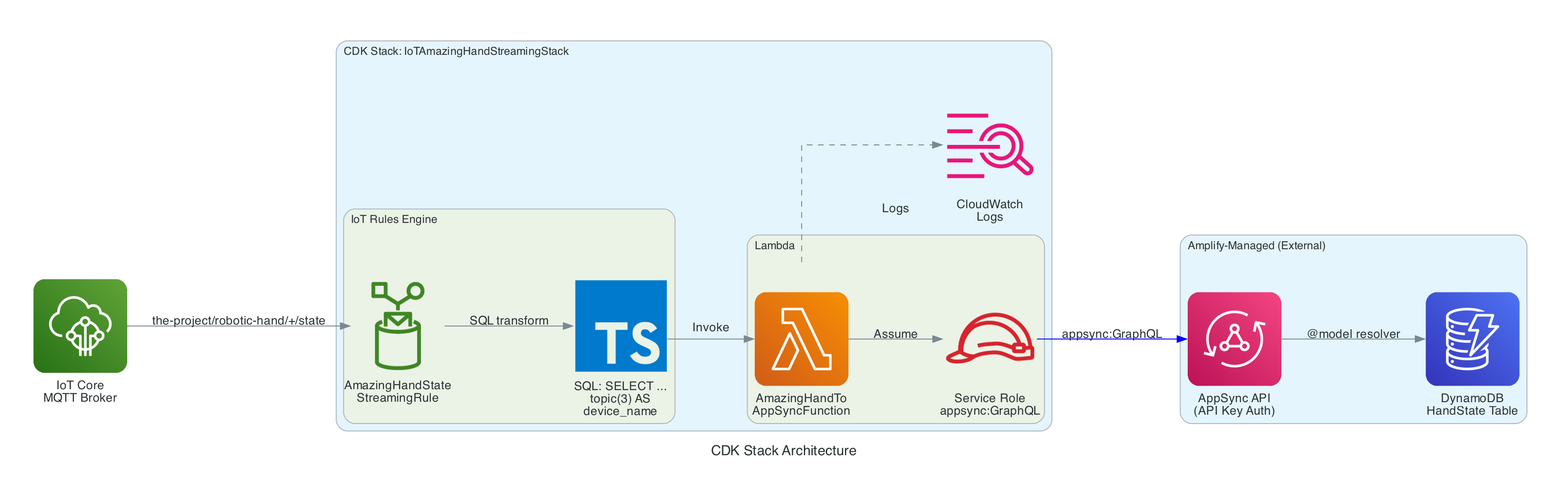
Architecture
The stack is intentionally small — a single IoT Rule, a single Lambda function, and the IAM glue to connect them. The AppSync API and DynamoDB table are managed by the Amplify Gen 2 backend in Part 1, so this stack only needs to call the existing createHandState mutation.
IoT Topic Rule (AmazingHandStateStreamingRule) — Matches MQTT messages on the-project/robotic-hand/+/state using SQL SELECT gesture, letter, ts, fingers, video_url, topic(3) AS device_name, then invokes the Lambda function
Lambda Function (AmazingHandToAppSyncFunction) — Node.js 18 function that receives the IoT event, flattens the nested fingers object into individual angle fields, and calls the AppSync createHandState GraphQL mutation using the Amplify v6 SDK with API Key authentication
Lambda IAM Role — Service role with AWSLambdaBasicExecutionRole for CloudWatch Logs and an inline policy granting appsync:GraphQL on the AppSync API
Lambda Permission — Allows the IoT service (iot.amazonaws.com) to invoke the Lambda function
Resources managed externally (by Amplify Gen 2 in Part 1):
AppSync API — GraphQL API with HandState model, createHandState mutation, and onCreateHandState subscription
DynamoDB Table — HandState table with auto-generated resolvers from the @model directive
The IoT Rule is the entry point. It listens on the MQTT topic pattern the-project/robotic-hand/+/state where + is a single-level wildcard matching any device name (e.g. XIAOAmazingHandRight).
The SQL query (using AWS IoT SQL version 2016-03-23) selects specific fields from the MQTT payload and enriches them with metadata extracted from the topic path:
The fingers object uses a nested structure with angle_1 and angle_2 per finger — representing the two joints of each finger on the Amazing Hand. This nested format is natural for the edge device to produce but needs to be flattened for the GraphQL schema.
The Lambda calls this mutation to persist the hand state and trigger the real-time subscription:
mutationCreateHandState($input:CreateHandStateInput!){ createHandState(input:$input){ id deviceName gesture letter indexAngle1 indexAngle2 middleAngle1 middleAngle2 ringAngle1 ringAngle2 thumbAngle1 thumbAngle2 timestamp videoUrl createdAt } }
When AppSync receives this mutation, two things happen:
The hand state record is persisted to DynamoDB via the auto-generated @model resolver
The onCreateHandStatesubscription is triggered, pushing the new record to all subscribed clients — including the React frontend from Part 1, which uses this data to update the 3D hand animation, signed letter history, and video feed in real-time
The entire stack is defined in approximately 74 lines of TypeScript. The stack accepts the AppSync API URL, API key, and API ID as props, which are injected via environment variables during deployment:
The stack creates the Lambda function with the AppSync connection details as environment variables, grants it appsync:GraphQL permissions scoped to the specific API, creates the IoT Topic Rule with the SQL query, and grants IoT permission to invoke the Lambda.
Two stack outputs are exported for reference:
AmazingHandIoTRuleArn — The IoT Rule ARN
AmazingHandLambdaFunctionArn — The Lambda function ARN
The project includes a GitHub Actions workflow (.github/workflows/aws-cdk-deploy.yml) that automates deployment:
Triggers on pushes to main and dev branches
Authenticates using OIDC (no static AWS credentials stored in GitHub)
Automatically discovers the AppSync configuration by:
Reading the Amplify App ID from SSM Parameter Store (/iot/amplify/amazinghand)
Finding the Amplify data CloudFormation stack
Extracting the AppSync API ID from CloudFormation stack resources, then querying the AppSync API directly for the URL and API key
Runs cdk deploy with the discovered values
This means the stack automatically stays connected to the correct AppSync API without manual configuration.
Technical Challenges & Solutions
Challenge 1: Flattening Nested IoT Payloads for GraphQL
Problem: The edge device publishes finger angles in a nested JSON structure (fingers.index.angle_1), but the AppSync GraphQL schema uses flat fields (indexAngle1). The IoT Rules Engine SQL can select nested objects but cannot rename nested fields into flat ones.
Solution: The Lambda function handles the transformation. It receives the nested fingers object from the IoT Rule and manually flattens each field with safe defaults (0 for missing angles, null for optional fields). This keeps the IoT Rule SQL simple and the edge device payload natural.
Challenge 2: Connecting to Amplify-Managed AppSync
Problem: The AppSync API is managed by Amplify Gen 2 in Part 1's repository, not by this CDK stack. The API URL, API key, and API ID change between environments and deployments.
Solution: The CI/CD pipeline automatically discovers the AppSync configuration at deploy time by reading from SSM Parameter Store and CloudFormation stack outputs. For local development, the values are passed via environment variables in deploy.sh. The CDK stack accepts them as typed props, keeping the infrastructure code clean.
Challenge 3: Extracting Device Name from MQTT Topic
Problem: The device name is part of the MQTT topic path (the-project/robotic-hand/XIAOAmazingHandRight/state), not the message payload. The Lambda needs it to set the deviceName field in the GraphQL mutation.
Solution: The IoT Rules Engine SQL function topic(3) extracts the 3rd segment of the topic path and aliases it as device_name. This is passed to the Lambda as part of the event, so the Lambda does not need to parse the topic itself. The wildcard + in the topic filter means this works for any device name without configuration changes.
git clone https://github.com/chiwaichan/cdk-iot-amazing-hand-streaming.git cd cdk-iot-amazing-hand-streaming npminstall cd lambda/amazing-hand-to-appsync &&npminstall&&cd../..
Deploy:
./deploy.sh
This bootstraps CDK (if needed) and deploys the stack with the AppSync configuration.
What's Next
In Part 3, I will cover the edge AI agent (strands-agents-amazing-hands) — a Strands Agent powered by Amazon Nova 2 Lite running on an NVIDIA Jetson that subscribes to the MQTT sentence text published by the frontend in Part 1, translates them into physical servo movements on the Pollen Robotics Amazing Hand for ASL fingerspelling, records video, and publishes hand state back to IoT Core — which this Part 2 stack routes through to AppSync for the frontend to consume.
Summary
This post covered the cloud infrastructure layer of the voice-to-sign-language translation system:
IoT Rules Engine listens on the-project/robotic-hand/+/state and extracts device name from the topic path using topic(3)
Lambda function flattens nested finger angle payloads (fingers.index.angle_1 → indexAngle1) and calls the AppSync createHandState GraphQL mutation
AppSync persists to DynamoDB and broadcasts onCreateHandState subscriptions to connected React clients in real-time
CDK stack is intentionally small (~74 lines) — it creates only the IoT Rule, Lambda, and IAM glue, relying on the Amplify-managed AppSync API from Part 1
CI/CD pipeline automatically discovers AppSync configuration from SSM Parameter Store, CloudFormation stack resources, and direct AppSync API calls — no manual configuration needed
The stack completes the real-time feedback loop: edge device publishes state → IoT Core → Lambda → AppSync → React frontend updates 3D hand animation
This is Part 1 of a 3-part series covering a real-time voice-to-sign-language translation system. The complete solution spans three separate repositories, each responsible for a distinct layer of the system:
This post (Part 1) - Frontend and Voice Processing — The React web app that captures speech, streams it to Amazon Nova 2 Sonic on Bedrock, publishes cleaned sentence text via MQTT, and renders a real-time 3D hand visualisation
Part 3 - Edge AI Agent (strands-agents-amazing-hands) — The Strands Agent powered by Amazon Nova 2 Lite running on an NVIDIA Jetson that receives MQTT sentence text, translates it to ASL servo commands, drives the Pollen Robotics Amazing Hand for fingerspelling, and streams video and state back
In this post, I focus on how speech enters the system, how Amazon Nova 2 Sonic processes and cleans up the spoken input, and how the frontend publishes cleaned sentence text over MQTT — setting the stage for Parts 2 and 3.
The key idea is that Nova 2 Sonic is not used as a chatbot here — it is configured as a dumb speech-to-text relay pipe that cleans up grammar, removes filler words like "um" and "uh", translates non-English speech to English, and forwards the cleaned text via a forced tool invocation (send_text) on every single utterance. The frontend then publishes the cleaned sentence text to AWS IoT Core over MQTT for the edge device to translate into ASL servo commands.
Goals
Capture speech in the browser and stream it to Amazon Nova 2 Sonic via bidirectional streaming — no backend servers required
Use Nova 2 Sonic's forced tool use (send_text) with toolChoice: { any: {} } to relay cleaned text on every utterance, not as a conversational chatbot
Publish cleaned sentence text to AWS IoT Core over MQTT for the edge device to translate into ASL servo commands
Subscribe to real-time hand state updates via GraphQL (AppSync) and synchronise a 3D Three.js hand animation with the physical hand
Use AWS Amplify Gen 2 for infrastructure-as-code backend definition in TypeScript (Cognito, AppSync, IAM policies)
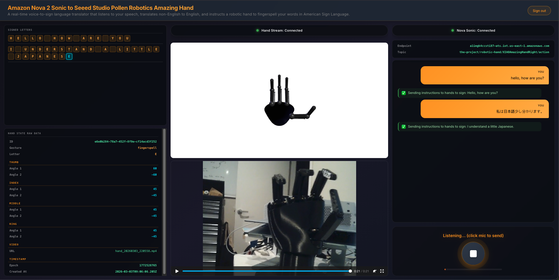
Display a 3-column UI with signed letter history, 3D hand animation with video feed, and live transcript with microphone controls
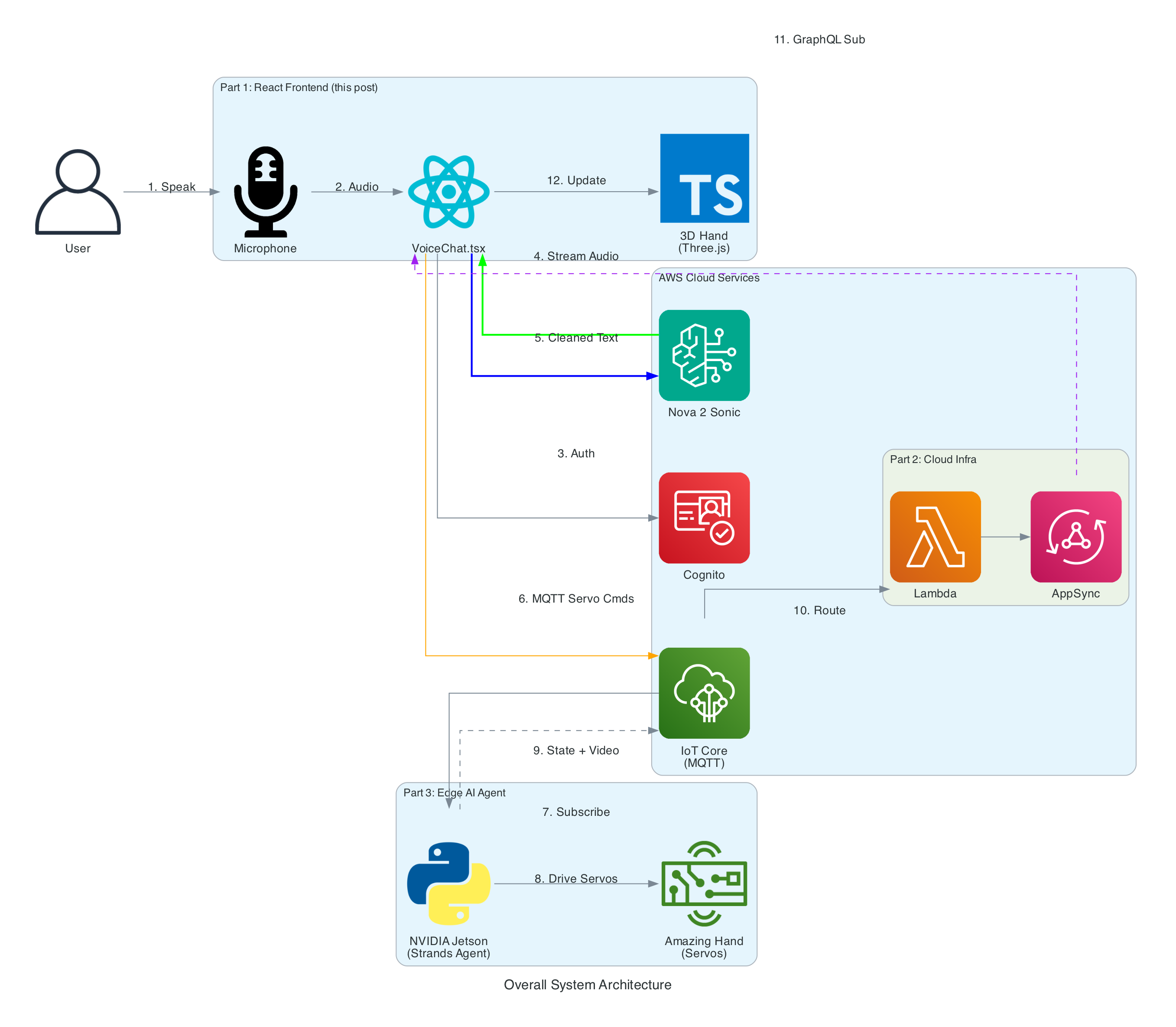
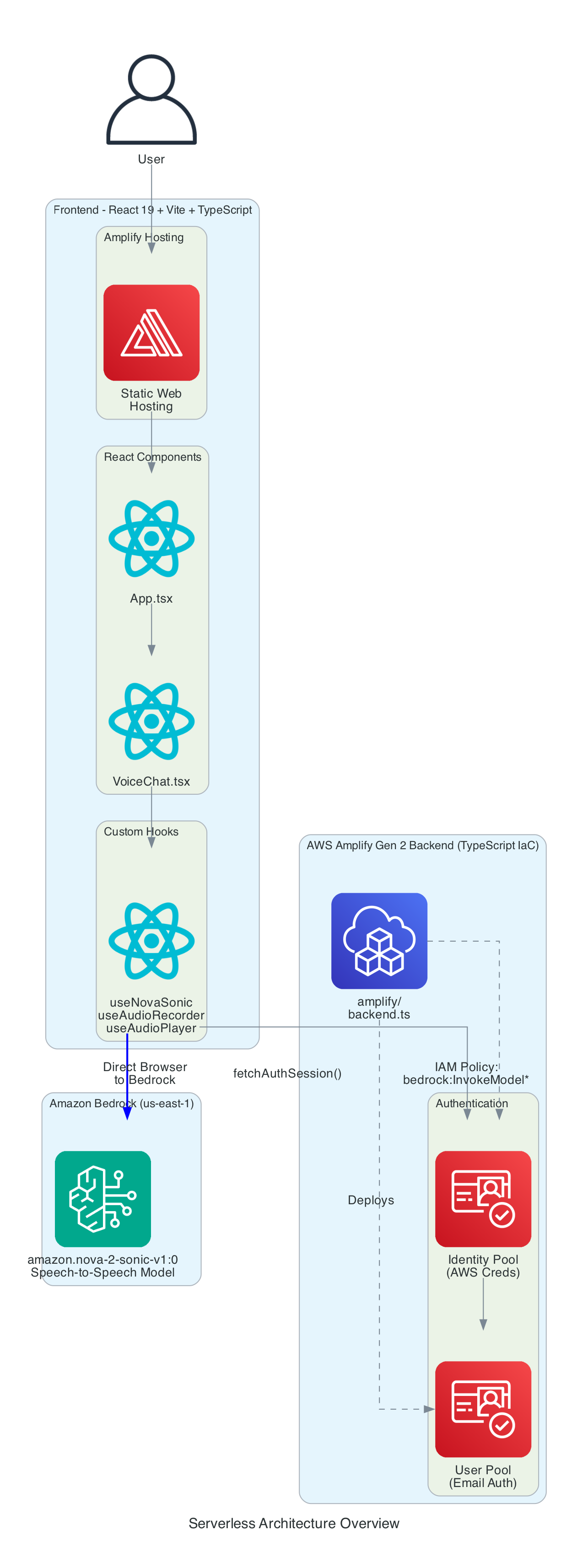
The Overall System
The end-to-end system takes spoken words from a browser microphone all the way through to physical ASL fingerspelling on an Amazing Hand — an open-source robotic hand designed by Pollen Robotics and manufactured by Seeed Studio — passing through cloud AI, IoT messaging, and an edge AI agent along the way.
System Components:
React Frontend (this post) - Captures speech, streams to Bedrock, publishes cleaned sentence text to MQTT, renders 3D hand animation synchronised with the physical hand via GraphQL subscriptions
Cloud Infrastructure (Part 2) - AWS CDK stack with IoT Core rules that route MQTT messages through Lambda to AppSync, enabling real-time GraphQL subscriptions between the edge device and the frontend
Edge AI Agent (Part 3) - Strands Agent powered by Amazon Nova 2 Lite on an NVIDIA Jetson that receives MQTT sentence text, translates it to ASL servo commands, drives the Amazing Hand for fingerspelling letter by letter, records video, and publishes hand state back via IoT Core
From user speech to ASL fingerspelling on the Amazing Hand
0/13
User
Browser
Bedrock
IoT Core
Jetson
Hand
Milestone
Complete
Total: 13 steps across 6 components (3 repos)
Speech → Sentence → Edge AI → ASL Fingerspelling
Architecture
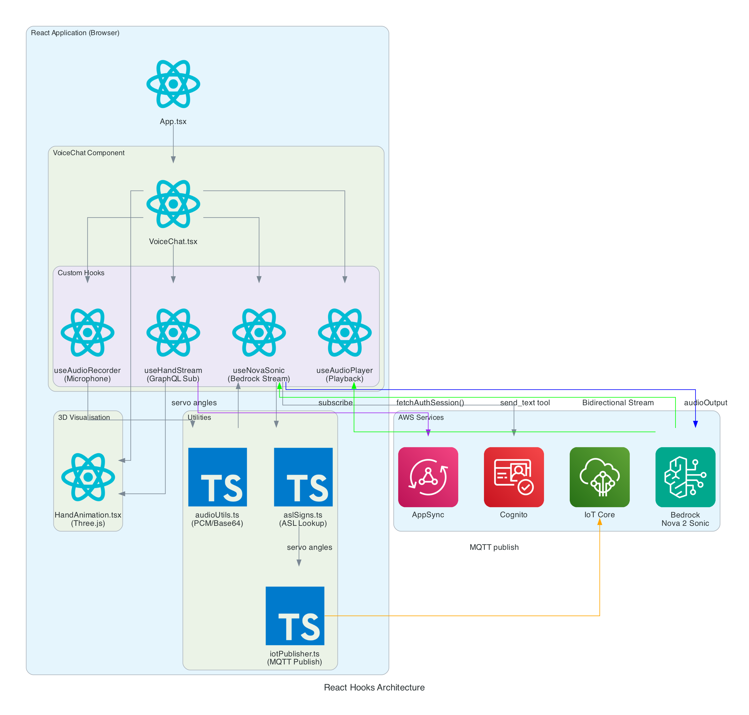
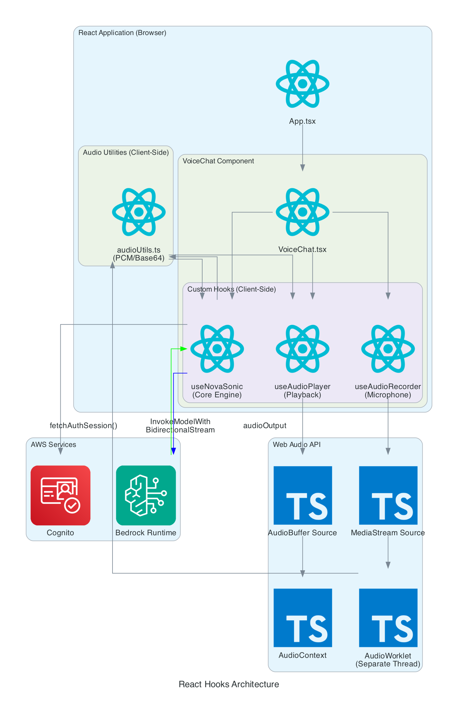
The frontend is built with React 19, Vite 7, and TypeScript 5.9. The application is structured around a main VoiceChat.tsx component that orchestrates four custom hooks, three utility modules, and a Three.js-based hand animation component.
VoiceChat.tsx - Main UI component with a 3-column responsive layout. Coordinates all hooks, renders the transcript feed, microphone controls, signed letter history, hand state data grid, video feed, and 3D animation. Collapses to a single column on screens under 1100px
useNovaSonic - Core hook managing the Bedrock bidirectional stream with InvokeModelWithBidirectionalStreamCommand. Handles authentication via Cognito, the Nova 2 Sonic event protocol (session/prompt/content lifecycle), the async generator input stream with backpressure, and send_text tool use responses. The tool is configured with toolChoice: { any: {} } to force tool invocation on every utterance
useAudioRecorder - Captures microphone input using an inline AudioWorklet running in a separate thread. Accumulates 2048 samples per buffer, resamples from the device sample rate (typically 48kHz) to 16kHz, converts Float32 to PCM16, and Base64 encodes for transmission
useAudioPlayer - Provides audio playback capability (FIFO queue of AudioBuffers at 24kHz). In the current implementation, Nova 2 Sonic's audio output is intentionally discarded since only the cleaned text via tool use is needed — the hook is available but not actively fed audio data
useHandStream - Subscribes to AppSync GraphQL onCreateHandState subscription filtered by device name. Fetches the last 20 hand states on mount and maintains a real-time list of 8 servo angles (thumb, index, middle, ring — each with two joint angles), letters, and video URLs
iotPublisher.ts - Publishes MQTT messages to the topic the-project/robotic-hand/XIAOAmazingHandRight/action. Publishes cleaned sentence text as { id, sentence, ts } payloads and handles IoT policy attachment to the Cognito identity
HandAnimation.tsx - Procedurally generated 3D robotic hand using Three.js with no external 3D models. The palm is built with LatheGeometry (curved cup shape), and each finger has a dual-joint rig (proximal + distal) with synchronised linkage. Uses WebGL rendering with PCFSoftShadowMap shadows, OrbitControls, and industrial-style materials with metalness/roughness
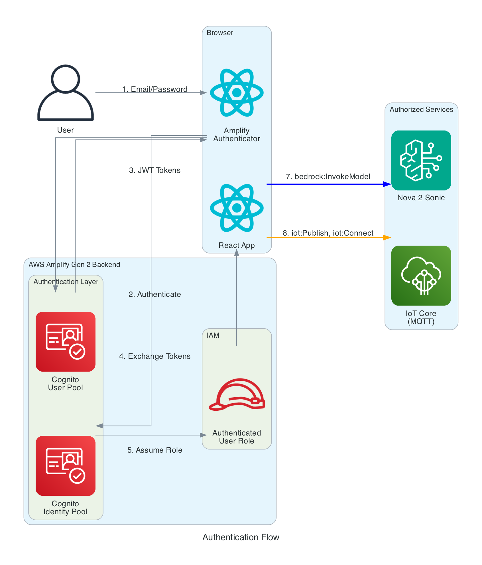
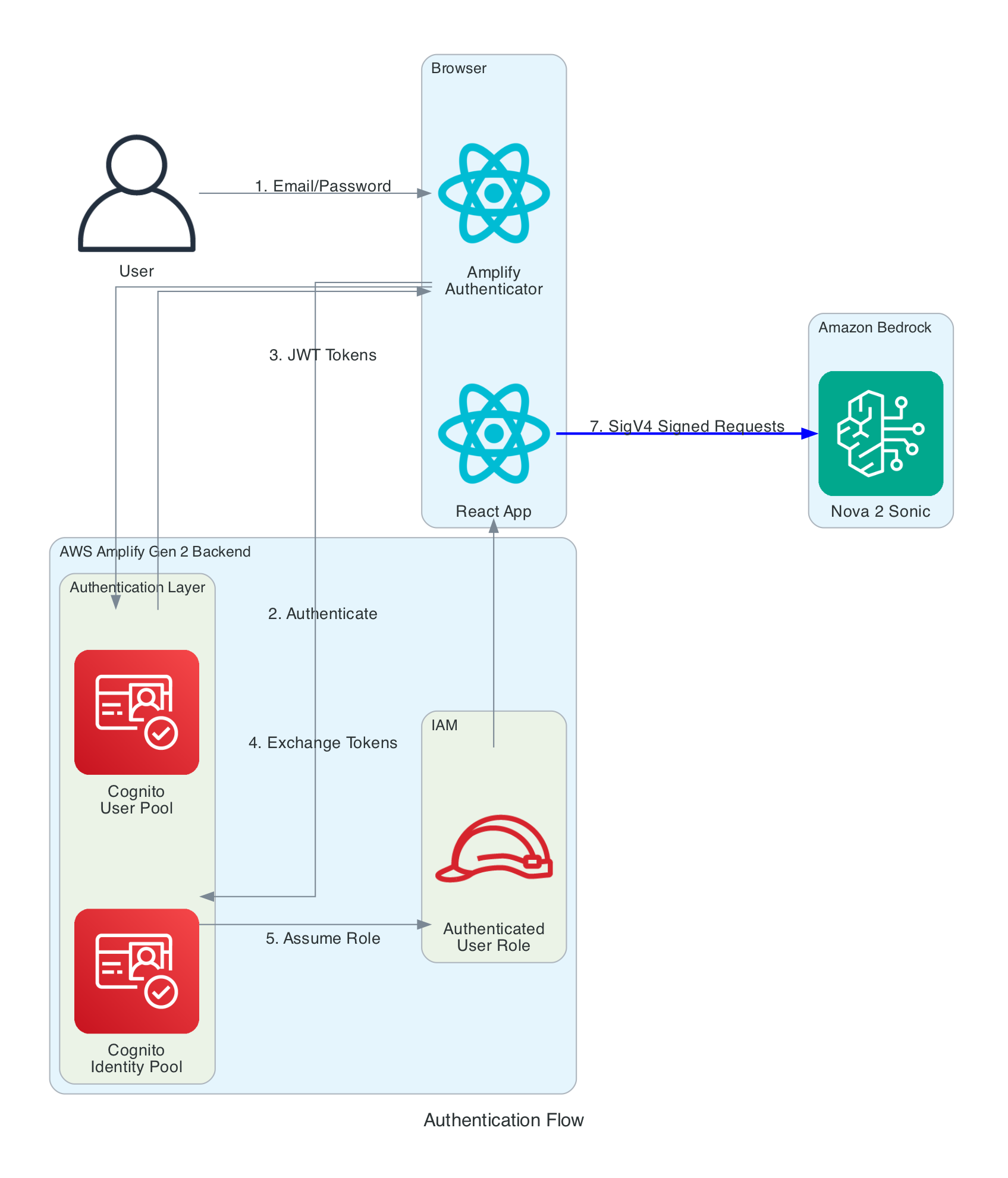
The frontend needs temporary AWS credentials to call both Bedrock (for Nova 2 Sonic streaming) and IoT Core (for MQTT publishing). No long-term credentials are stored in the browser.
Authentication Layers:
Cognito User Pool - Handles user registration and login with email/password. Configured via Amplify Gen 2 defineAuth with preferredUsername as an optional attribute
Cognito Identity Pool - Exchanges JWT tokens from the User Pool for temporary AWS credentials (access key, secret key, session token). Credentials are automatically refreshed by the Amplify SDK before expiration
IAM Role - The authenticated user role grants two sets of permissions: bedrock:InvokeModel and bedrock:InvokeModelWithResponseStream scoped to amazon.nova-2-sonic-v1:0 in us-east-1, and iot:Publish, iot:Connect, iot:DescribeEndpoint, and iot:AttachPolicy for IoT Core MQTT access. An IoT Core policy (RoboticHandPolicy) is also attached to the Cognito identity at runtime to authorise MQTT publishing to the the-project/robotic-hand/* topic pattern
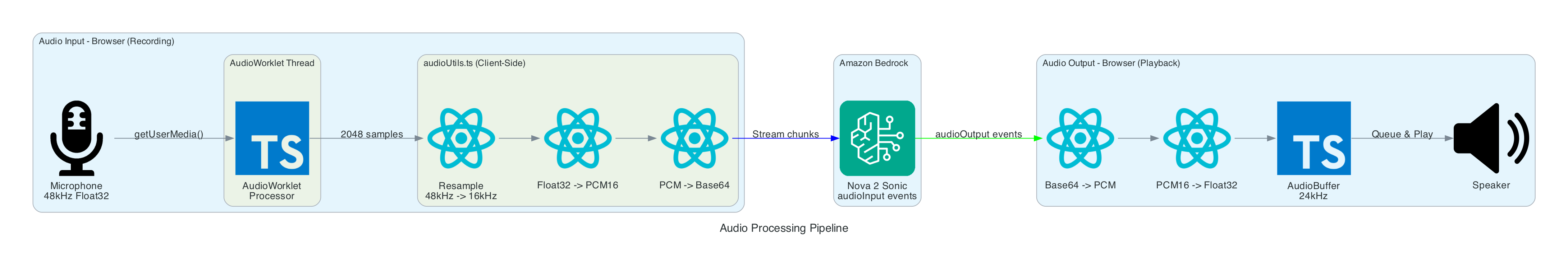
The browser captures audio from the microphone using the Web Audio API and an AudioWorklet running in a separate thread. The AudioWorklet avoids main-thread blocking and processes audio in real-time with echo cancellation and noise suppression enabled.
Input Processing (Recording):
Microphone - Browser calls getUserMedia() to capture audio at the device's native sample rate (typically 48kHz) with mono channel, echo cancellation, and noise suppression enabled
AudioWorklet - An inline AudioCaptureProcessor (loaded as a Blob URL to avoid CORS issues) runs in a separate thread. It accumulates samples in a buffer and posts a Float32Array message to the main thread every 2048 samples
Resample - Linear interpolation resampling converts from 48kHz to 16kHz (Nova 2 Sonic's required input rate). The ratio is calculated dynamically from the actual device sample rate
Float32 to PCM16 - Floating point samples in the range [-1, 1] are converted to 16-bit signed integers. Negative values are multiplied by 0x8000 and positive values by 0x7FFF
Base64 Encode - The binary PCM data is encoded to Base64 text for JSON transmission to Bedrock via a custom uint8ArrayToBase64() utility that iterates bytes into a binary string and then calls btoa()
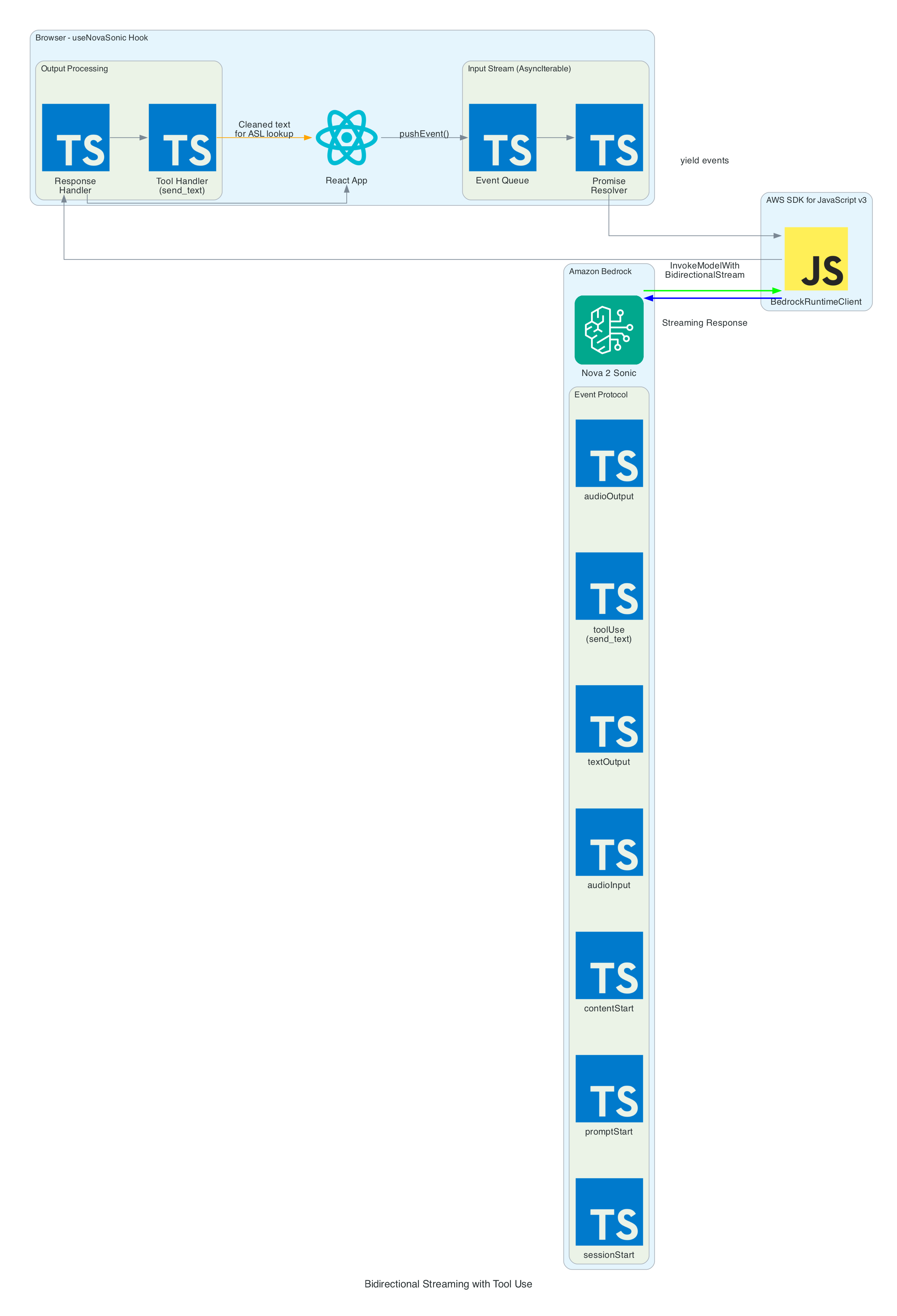
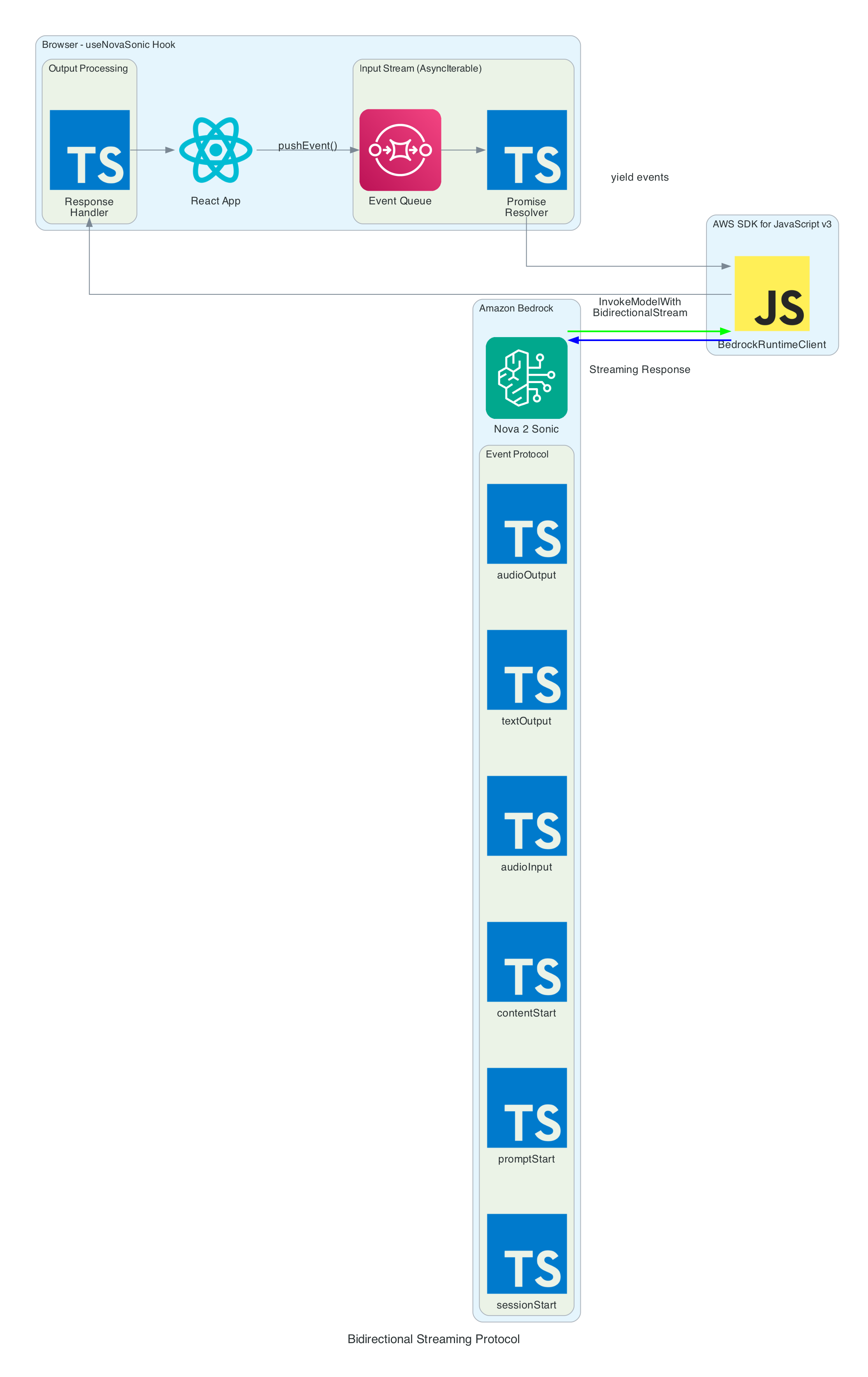
The heart of the system is the bidirectional stream to Amazon Nova 2 Sonic using InvokeModelWithBidirectionalStreamCommand. Nova 2 Sonic is configured not as a chatbot, but as a speech relay that cleans up input and forwards it via forced tool use.
Input Events (sent to Bedrock):
sessionStart - Initialises the session with inference configuration: maxTokens: 1024, topP: 0.9, temperature: 0.7
promptStart - Configures audio output format: audio/lpcm at 24kHz, 16-bit, mono, voice matthew, Base64 encoding. Also defines the send_text tool with toolChoice: { any: {} } to force tool invocation on every utterance
contentStart (TEXT) - Sends the system prompt that instructs Nova 2 Sonic to act as a "dumb speech-to-text relay pipe" — clean up grammar, remove filler words, translate non-English to English, call send_text with the cleaned text, then respond with only "Sent"
contentStart (AUDIO) - Marks the beginning of audio input content
audioInput - Streams Base64-encoded 16kHz PCM audio chunks in real-time as the user speaks
contentEnd / promptEnd / sessionEnd - Lifecycle events to terminate content blocks, prompts, and sessions
Output Events (received from Bedrock):
textOutput - Returns transcribed user speech and the generated AI response text ("Sent")
toolUse - The send_text tool invocation containing the cleaned text in { sentence: "..." } format. This is the primary output — the frontend publishes the sentence to MQTT for the edge device to translate into ASL servo commands
audioOutput - Synthesised voice response as Base64-encoded 24kHz PCM. In the current implementation, audio output is intentionally discarded since only the cleaned text via tool use is needed
Tool Use — send_text:
The tool is defined with toolChoice: { any: {} }, which forces Nova 2 Sonic to call it on every single utterance without exception
The tool accepts a single sentence parameter — the cleaned-up, well-formed sentence
When the tool invocation arrives, the frontend extracts the sentence and publishes it as { id, sentence, ts } to IoT Core via MQTT using publishSentence(). The edge device then translates the sentence into ASL servo commands
A JSON tool result ({ "status": "success", "sentence": "..." }) is sent back to Nova 2 Sonic to complete the tool use cycle
Once the cleaned sentence is extracted from the send_text tool invocation, iotPublisher.ts publishes it to the MQTT topic the-project/robotic-hand/XIAOAmazingHandRight/action via AWS IoT Core.
The payload is a simple JSON object containing:
id - A UUID for the message
sentence - The cleaned sentence text from Nova 2 Sonic
ts - Unix timestamp in seconds
The edge device (covered in Part 3) receives this sentence and is responsible for translating it into ASL servo commands and driving the physical hand.
From Nova 2 Sonic text output to IoT Core sentence publish
0/7
Nova
Hook
VoiceChat
Publisher
IoT Core
Milestone
Sentence Publish Pipeline
Speech → Nova 2 Sonic cleanup → send_text tool use → publishSentence → MQTT to edge device
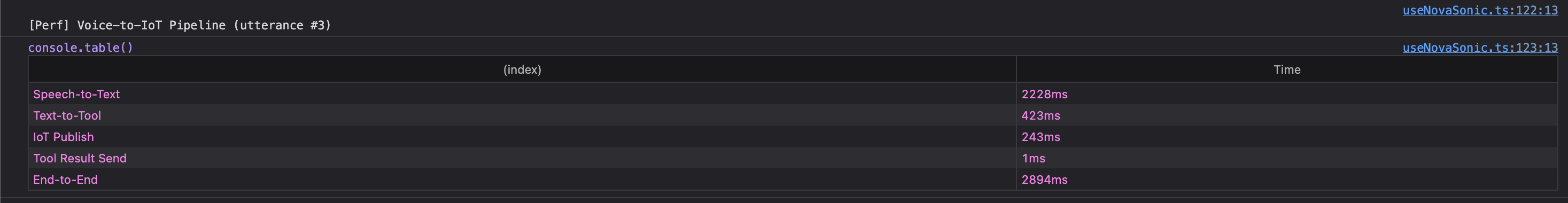
The browser console logs the performance breakdown for each utterance through the voice-to-IoT pipeline. In this example, the end-to-end time from speech detection to IoT publish is approximately 2.9 seconds — with the majority spent on Speech-to-Text (2228ms) as Nova 2 Sonic processes the audio, followed by Text-to-Tool extraction (423ms) and IoT Publish (243ms):
The frontend subscribes to AppSync's onCreateHandState GraphQL subscription to receive real-time updates from the edge device. Each update includes the device name, current letter being signed, all 8 servo angles (thumb, index, middle, ring — each with two joint angles), a timestamp, and an optional video URL.
On mount, the hook fetches the last 20 hand states to populate the UI immediately. New states arrive in real-time as the edge device publishes them back through IoT Core → Lambda → AppSync. The data is displayed in both the signed letter history panel and the raw hand state data grid.
The HandAnimation.tsx component renders a procedurally generated 3D robotic hand using Three.js — no external 3D models are loaded. The entire hand is built from code:
The palm uses LatheGeometry to create a curved cup shape that tapers from a narrow wrist (radius 0.18) to wide knuckles (radius 0.56)
Each finger has a dual-joint rig with proximal and distal segments, knuckle joints, linkage bars, and fingertips. The thumb is mounted on the side of the palm and rotates on the Z-axis, while the index, middle, and ring fingers are mounted on the front rim and rotate on the X-axis
The distal joint automatically follows the proximal joint at 50% of its angle, simulating a synchronised linkage mechanism
Materials use industrial-style metalness/roughness: dark gray frame (0x2a2a2a), light gray joints (0x888888), and darker gray tips (0x555555)
The scene includes PCFSoftShadowMap shadows, ambient lighting (0.8), directional light (1.0), and a fill light (0.4), with OrbitControls for interactive zoom and rotation
Servo angle updates from the GraphQL subscription drive the finger rotations in real-time, keeping the 3D animation synchronised with the physical Amazing Hand.
The useAudioPlayer hook provides a FIFO queue-based audio playback capability for Web Audio AudioBuffer objects at 24kHz. However, in the current implementation, Nova 2 Sonic's audio output is intentionally discarded — the onAudioOutput callback is set to a no-op since only the cleaned text via the send_text tool use is needed to drive the MQTT pipeline. The hook remains available for future use if audio feedback is desired.
Problem: Loading an AudioWorklet processor from an external JavaScript file fails with CORS errors on some deployments, particularly when using Amplify Hosting.
Solution: Inline the AudioWorklet code as a Blob URL. The processor code is defined as a string, converted to a Blob with type application/javascript, and loaded via URL.createObjectURL(). The object URL is revoked after the module is added:
Problem: Nova 2 Sonic is a conversational model by default — it wants to chat and respond naturally. But in this system, it needs to act as a pure relay, forwarding every single utterance as cleaned text without adding commentary or refusing any messages.
Solution: A combination of system prompt engineering and forced tool use. The system prompt explicitly instructs Nova 2 Sonic to act as a "dumb speech-to-text relay pipe" and never add commentary. The send_text tool is configured with toolChoice: { any: {} }, which forces the model to invoke a tool on every response. After calling the tool, it is instructed to only respond with "Sent".
Problem: The system needs to transmit the user's intent from the frontend to the edge device reliably via IoT Core MQTT.
Solution: Rather than translating text to servo commands on the frontend (which would require large payloads with many servo poses), the frontend publishes only the cleaned sentence text as a compact { id, sentence, ts } JSON payload. The edge device is responsible for translating the sentence into ASL servo commands, keeping the MQTT messages small and the frontend simple.
Enable Nova 2 Sonic in Bedrock Console (us-east-1 region)
Clone and Install:
git clone https://github.com/chiwaichan/amplify-react-nova-sonic-voice-chat-amazing-hand.git cd amplify-react-nova-sonic-voice-chat-amazing-hand npminstall
Start Amplify Sandbox:
npx ampx sandbox
Run Development Server:
npm run dev
Open Application:
Navigate to http://localhost:5173, create an account, and start talking. Note that the full system requires Parts 2 and 3 to be deployed for the physical hand to respond — but the frontend will still capture speech, process it through Nova 2 Sonic, and display the 3D hand animation independently.
What's Next
In Part 2, I will cover the cloud infrastructure layer — the AWS CDK stack (cdk-iot-amazing-hand-streaming) that routes IoT Core MQTT messages through Lambda to AppSync. This is the bridge that enables real-time GraphQL subscriptions, allowing the frontend to receive hand state updates from the edge device as they happen.
In Part 3, I will cover the edge AI agent (strands-agents-amazing-hands) — a Strands Agent powered by Amazon Nova 2 Lite running on an NVIDIA Jetson that subscribes to the MQTT sentence text published by this frontend, translates them into physical servo movements on the Pollen Robotics Amazing Hand for ASL fingerspelling, records video of the hand in action, and publishes state back through IoT Core.
Summary
This post covered the frontend and voice processing layer of a real-time voice-to-sign-language translation system:
Amazon Nova 2 Sonic is used not as a chatbot but as a speech relay — configured via system prompt and toolChoice: { any: {} } forced send_text tool use to clean up grammar, remove filler words, translate to English, and forward every utterance as text
Audio pipeline captures at 48kHz via AudioWorklet, resamples to 16kHz, converts to PCM16 Base64 for Bedrock input. Nova 2 Sonic's audio output is intentionally discarded since only the cleaned text is needed
MQTT publishing sends cleaned sentence text as { id, sentence, ts } to AWS IoT Core for the edge device to translate into ASL servo commands
Real-time feedback via GraphQL subscriptions keeps the 3D Three.js hand animation synchronised with the physical Amazing Hand using 8 servo angles (thumb, index, middle, ring — each with two joints)
Fully serverless frontend using AWS Amplify Gen 2 with Cognito authentication, no backend servers — direct browser-to-Bedrock and browser-to-IoT Core communication
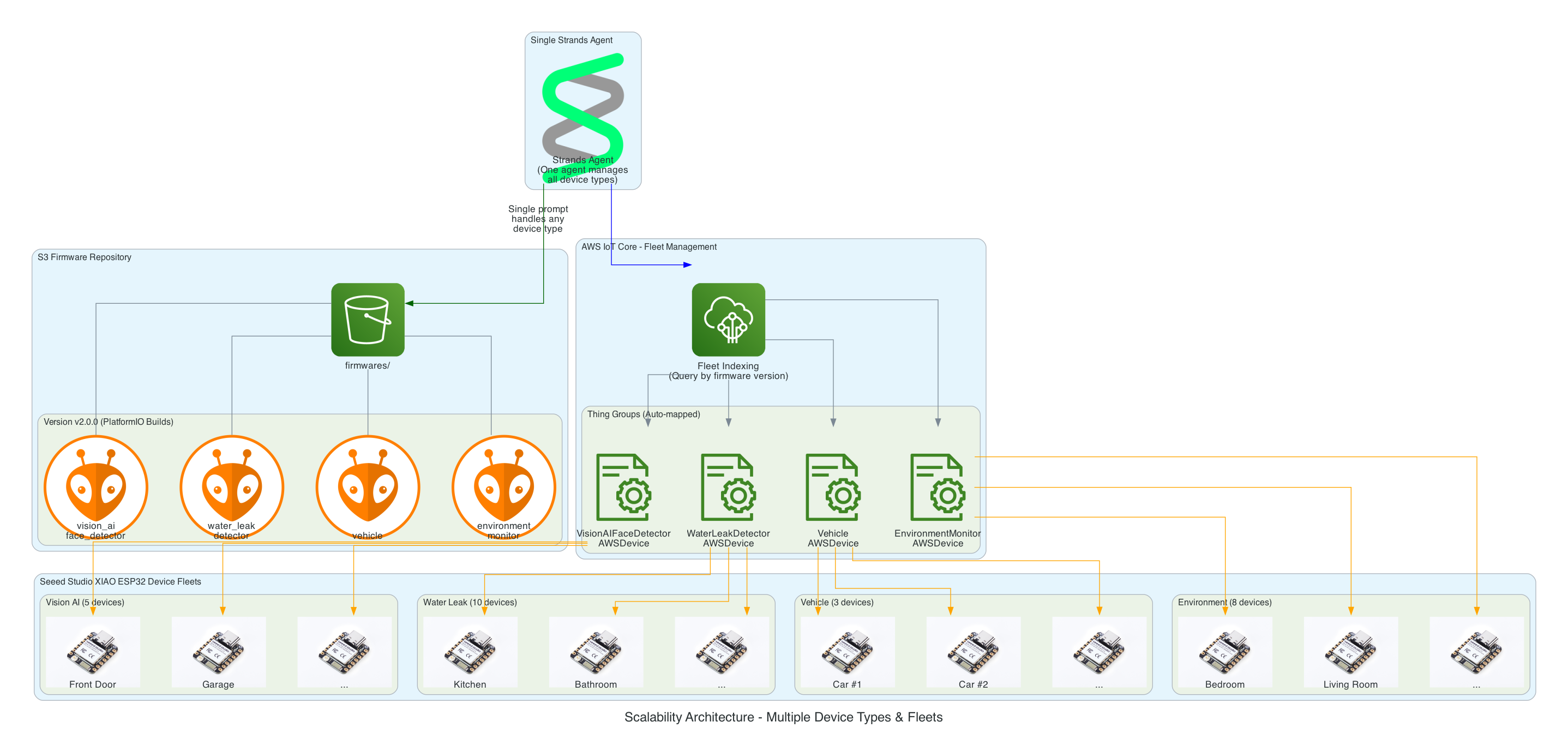
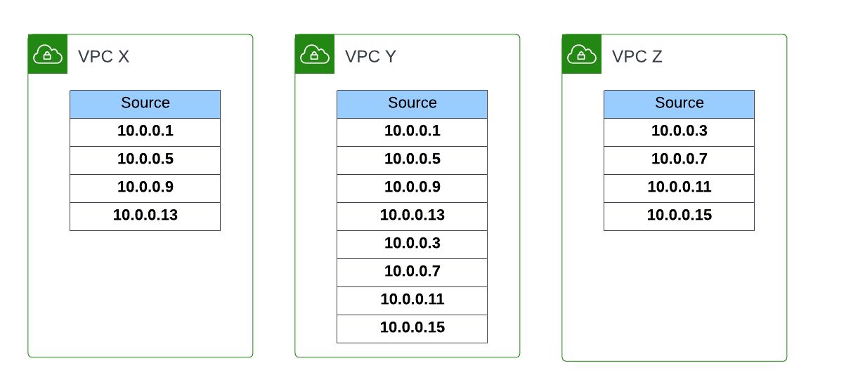
I want to have the ability to be able to manage the firmware of all IoT devices using a prompt - it could be to upgrade a device to the latest version, or even to perform a rollback, whether across the entire IoT device fleet level - every device in all 20+ solution types, all the devices within a type of solution, or even at an individual device level.
Goals
To be able to over-the-air flash a new firmware version using a prompt
To have an Agentic Agent do all the work, give it a prompt and it takes cares of the rest
Scalable in the number of IoT devices, as well as, being able to scale as the number of new IoT solution Types increases; with no effort required - implement once and forget
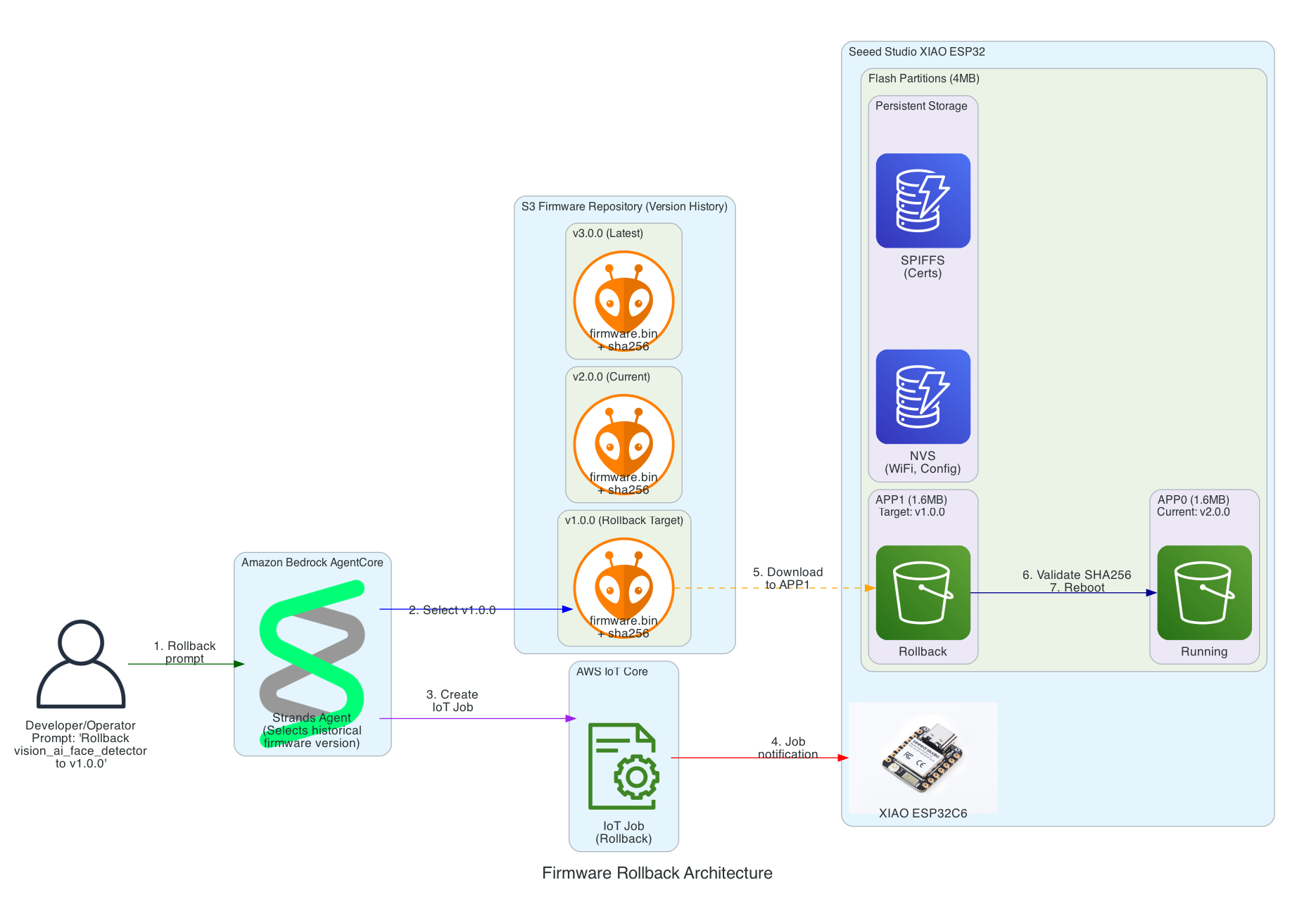
Have the ability to rollback to any firmware version specified in the prompt
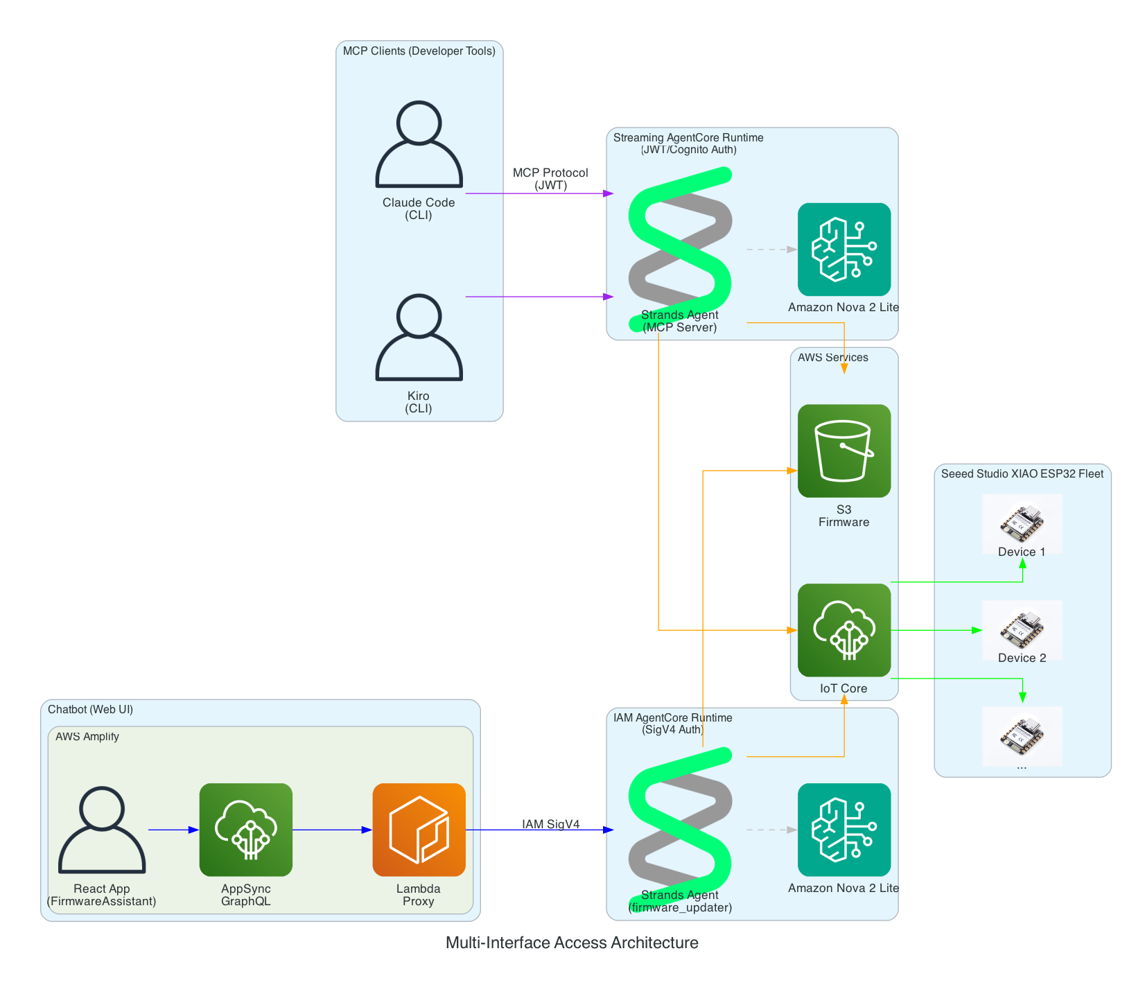
This same solution can be interfaced with using the Model Context Protocol (MCP): whether via Kiro CLI or Claude Code
This same solution can be interfaced with using a chatbot
Must be authenticated to interface with this solution
Must be a completely serverless-solution
Firmware integrity verification using SHA256 checksums before flashing to ensure firmware hasn't been corrupted during download
Safe rollout with rate limiting and automatic abort thresholds to prevent fleet-wide failures
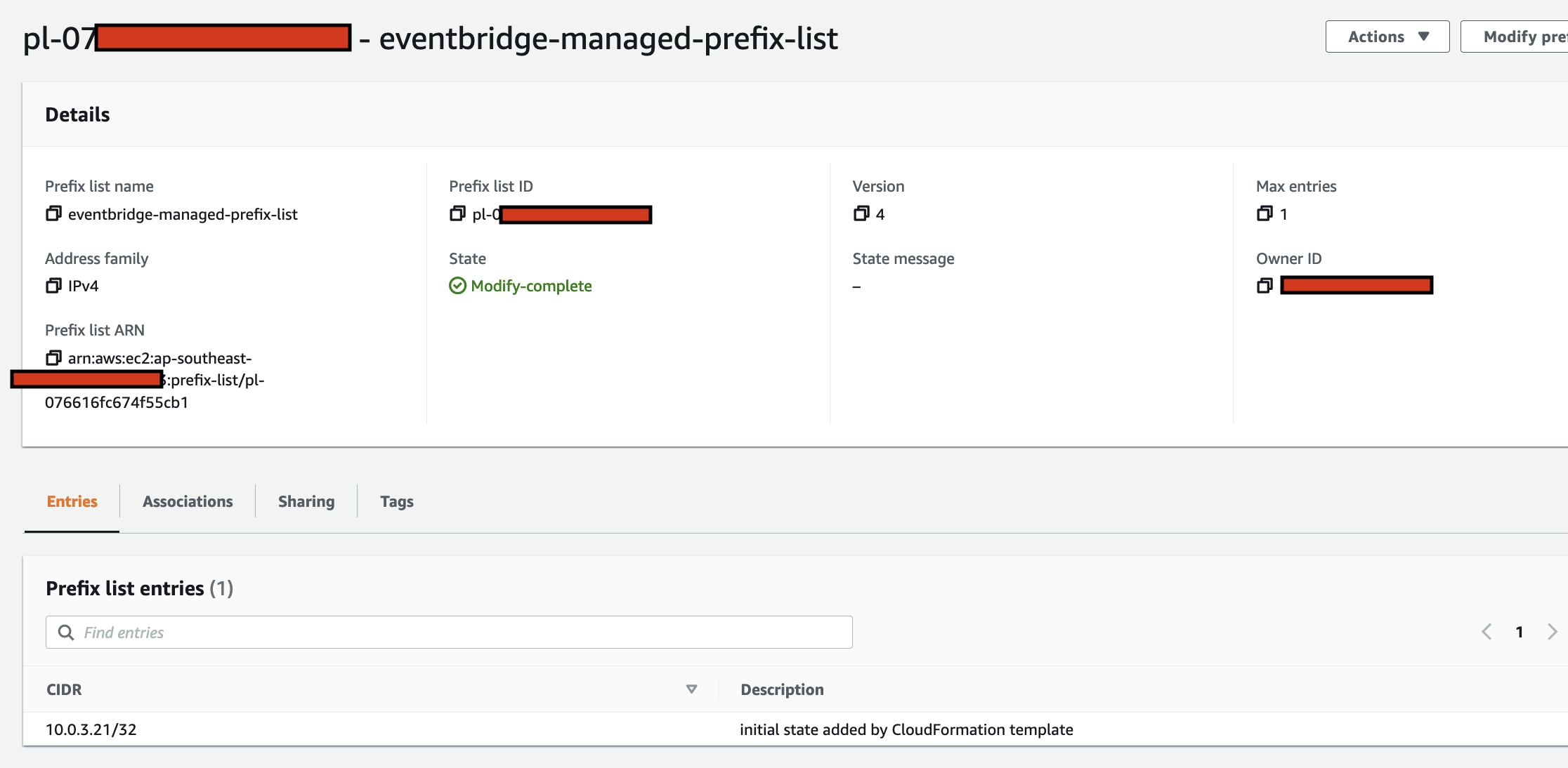
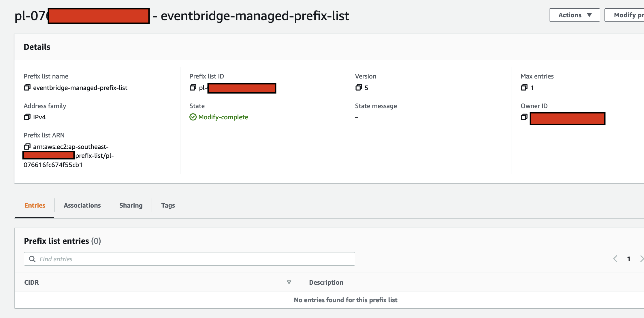
Device firmware version tracking via device shadows to enable version-based targeting for updates
Configuration-gated deployments to enable or disable OTA updates per device type for controlled rollouts
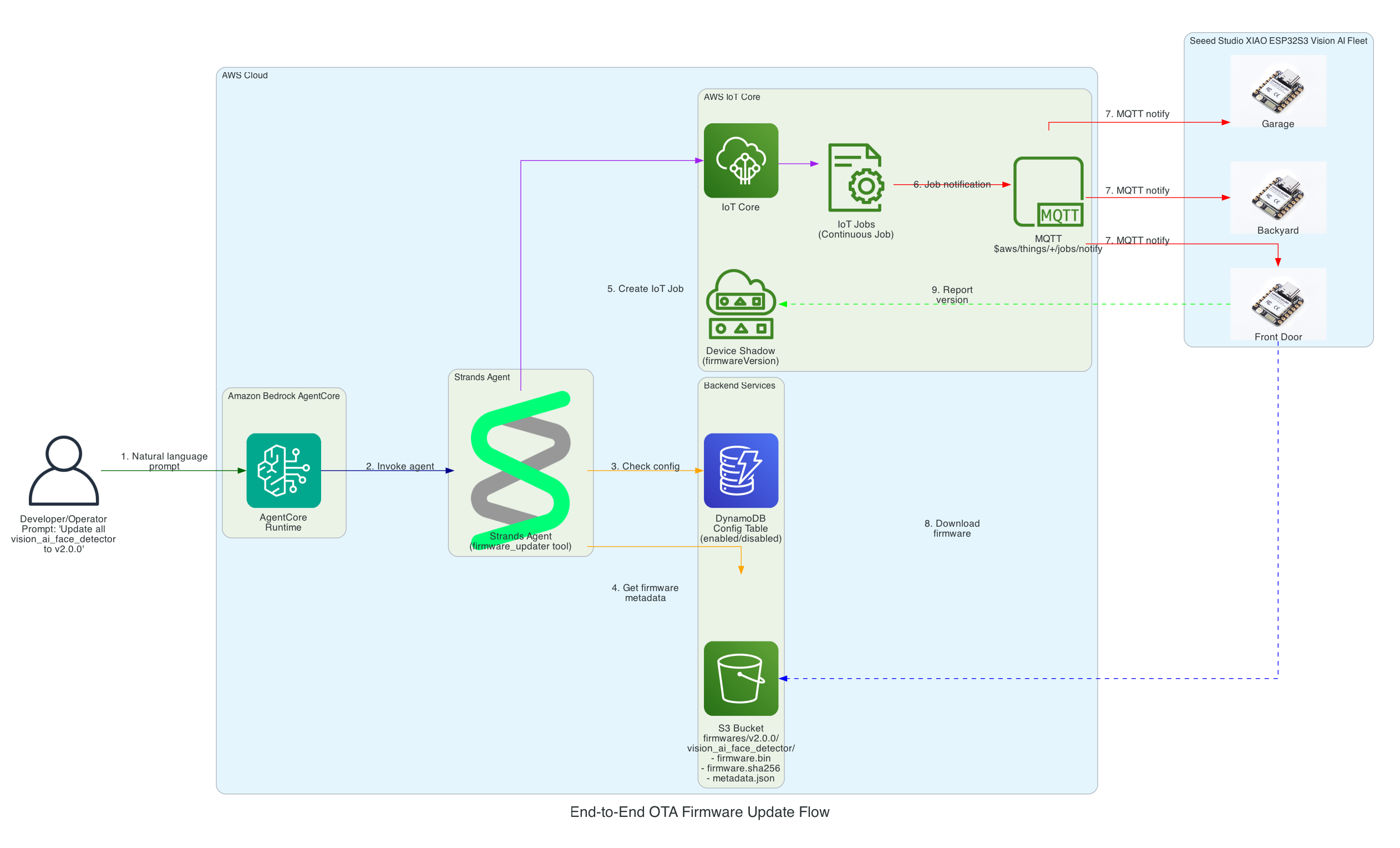
From natural language prompt to firmware flashed on Seeed Studio XIAO ESP32
0/15
User
AgentCore
Strands
DynamoDB
S3
IoT Core
XIAO
Milestone
Complete
Total: 15 message exchanges across 7 participants
~12 seconds end-to-end (prompt to firmware flashed)
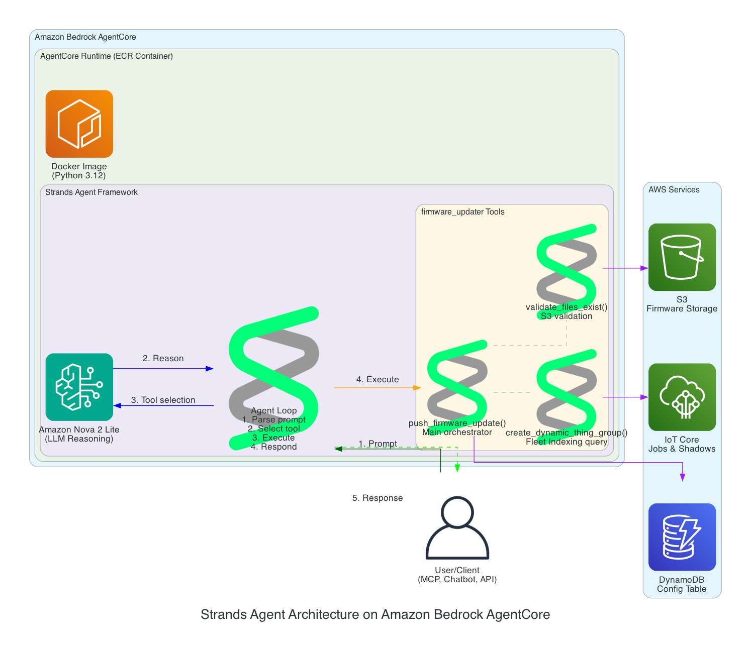
Strands Agent Architecture on Amazon Bedrock AgentCore
This diagram details the internal architecture of the Strands Agent running on Amazon Bedrock AgentCore, showing how the LLM reasons about prompts and orchestrates tool execution.
Components:
Amazon Bedrock AgentCore - Managed runtime that hosts and scales the agent
This diagram shows how the solution enables rollback to any previous firmware version using a simple prompt, leveraging the dual-partition architecture of the Seeed Studio XIAO ESP32.
Key Rollback Features:
Version History in S3 - All firmware versions are retained (v1.0.0, v2.0.0, v3.0.0, etc.) enabling rollback to any point
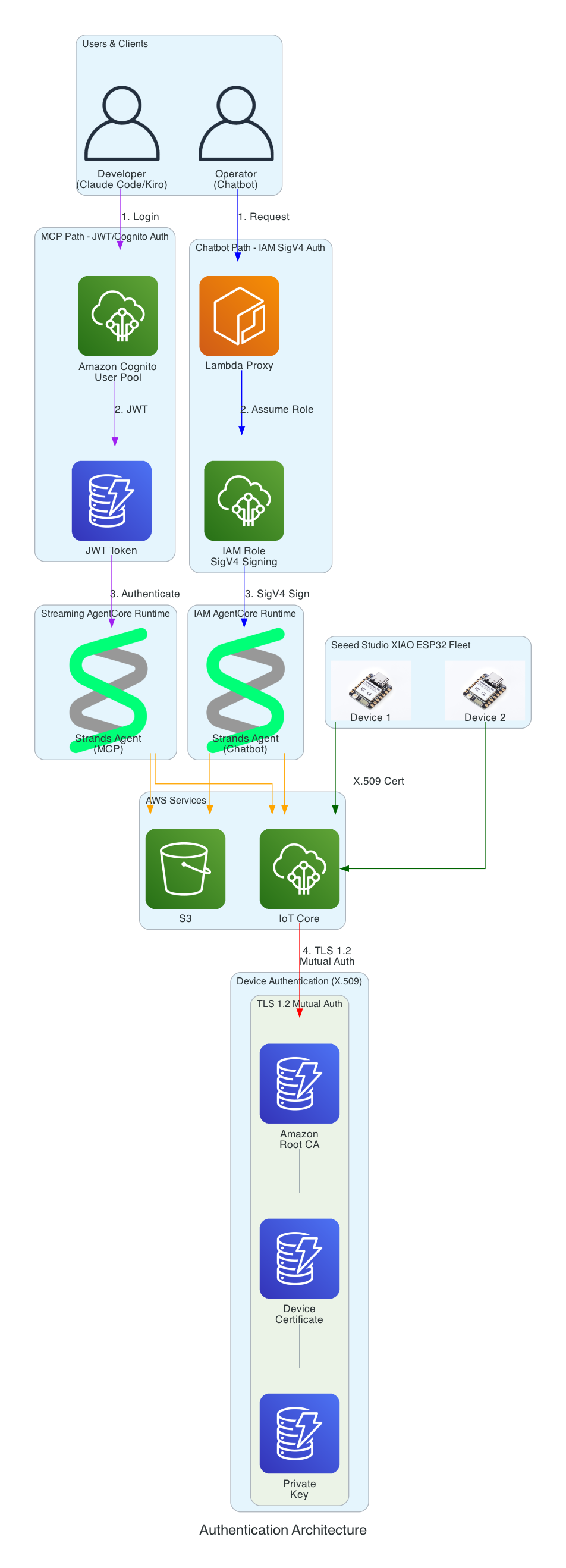
This diagram demonstrates how the Strands Agent can be accessed through multiple interfaces with different authentication methods - enabling developers to use their preferred tools while operators can use a web-based chatbot.
Interface Options:
MCP Clients (Developer Tools) - Claude Code and Kiro CLI connect via Model Context Protocol to a Streaming AgentCore Runtime using JWT/Cognito authentication
Chatbot (Web UI) - AWS Amplify React app with FirmwareAssistant component connects via Lambda proxy to an IAM AgentCore Runtime using SigV4 authentication for service-to-service communication
Two Runtimes, Same Agent Logic - Both runtimes run the same Strands Agent code but are deployed separately with different authentication methods suited to their use cases
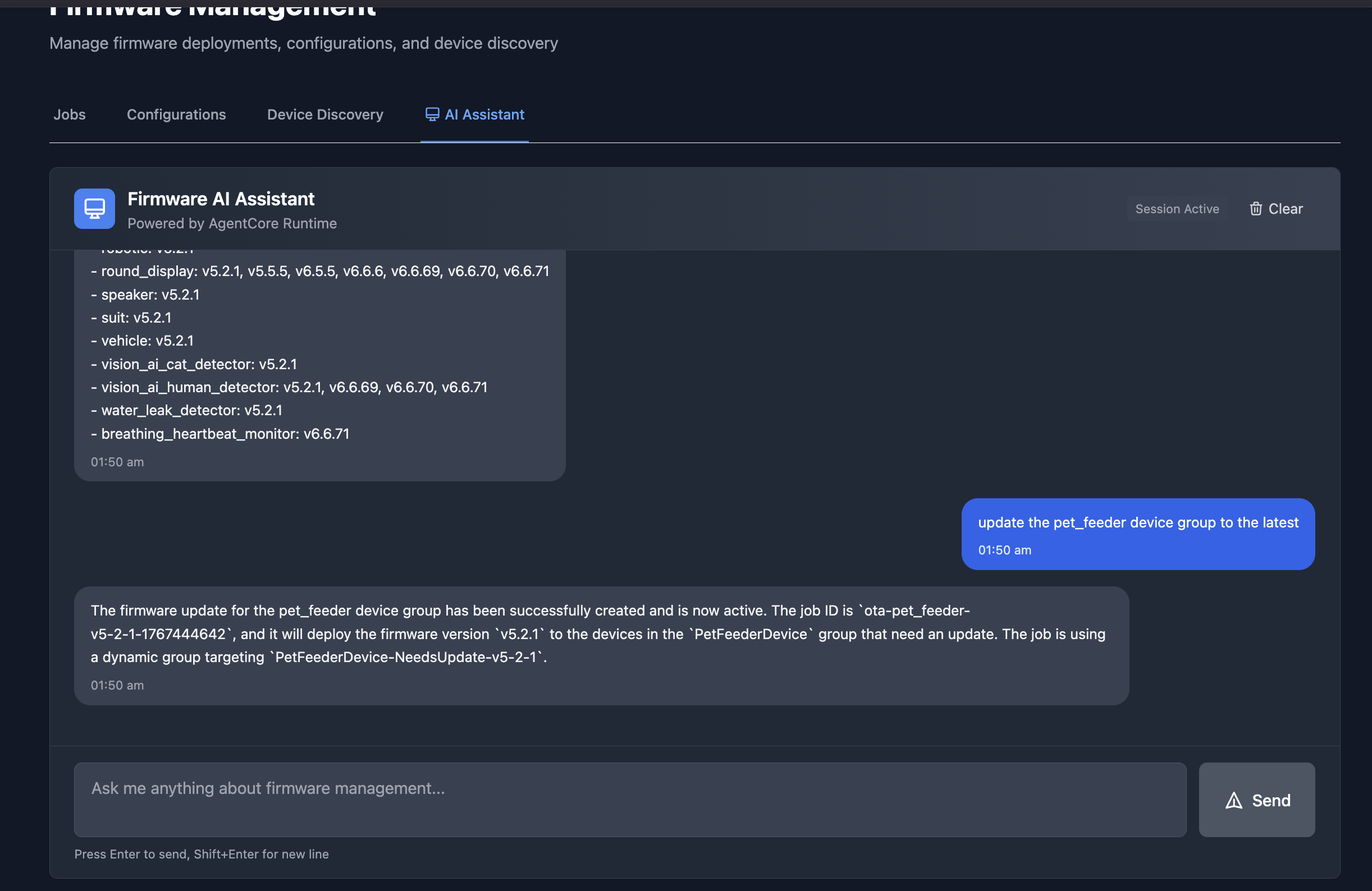
The chatbot interface in an Amplify React App provides a conversational way to manage firmware updates. In this example, the assistant lists all available firmware versions across device groups, and then creates an OTA job to update the pet_feeder device group to the latest firmware version.
This diagram illustrates the multi-layer security model ensuring that all access to the firmware management system is properly authenticated. Each interface uses a different authentication method suited to its use case.
Authentication Layers:
Cognito JWT (MCP Path) - Developers using Claude Code and Kiro CLI authenticate via Amazon Cognito User Pool and receive JWT tokens, connecting to the Streaming AgentCore Runtime
IAM SigV4 (Chatbot Path) - The Lambda proxy authenticates using AWS IAM roles with SigV4 request signing for service-to-service communication with the IAM AgentCore Runtime
X.509 Certificates (Device Path) - XIAO ESP32 devices authenticate to AWS IoT Core using TLS 1.2 mutual authentication with per-device certificates
Certificate Chain - Amazon Root CA validates device certificates stored in SPIFFS (survives firmware updates)
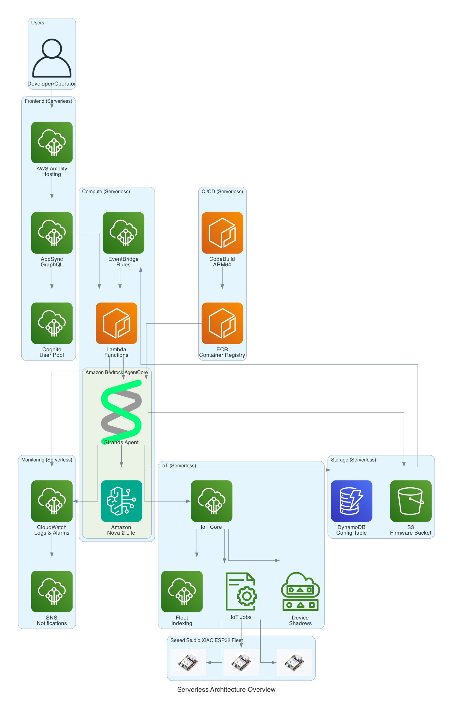
This diagram provides a comprehensive view of all AWS services used in the solution - every component is fully serverless with no EC2 instances to manage.
Serverless Components:
Frontend - AWS Amplify Hosting, AppSync GraphQL, Cognito User Pool
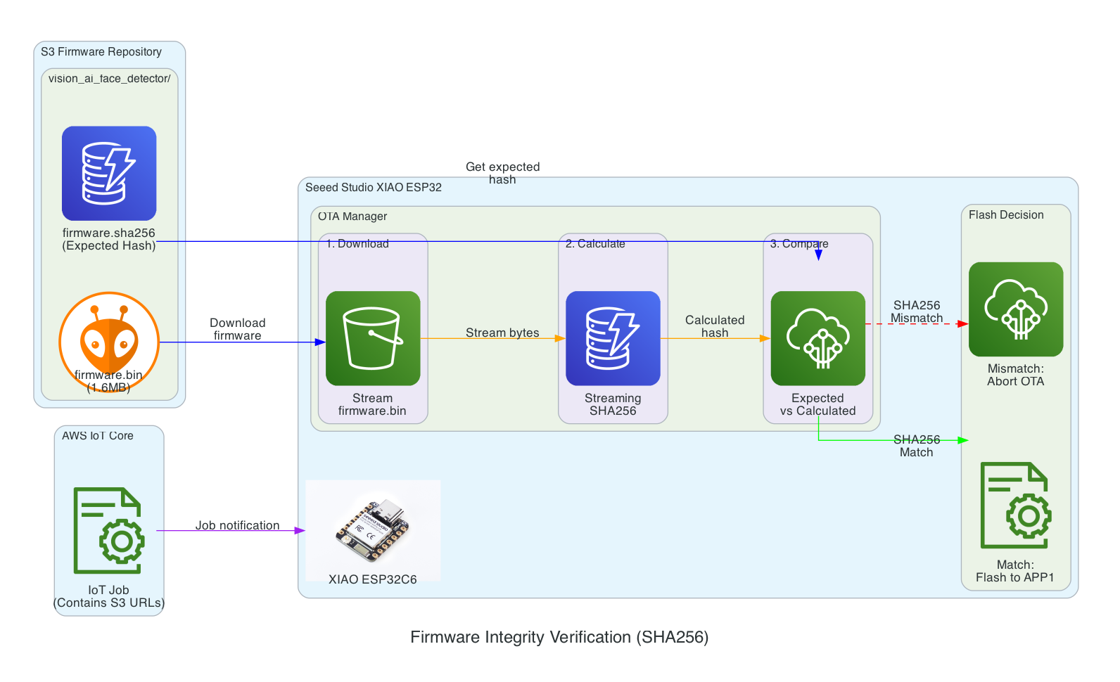
This diagram shows the firmware integrity verification process that ensures firmware hasn't been corrupted during download before flashing to the device.
Verification Flow:
Download - XIAO ESP32 streams firmware.bin from S3 in chunks
Calculate - SHA256 hash is calculated progressively during download (streaming hash)
Compare - Calculated hash is compared against expected hash from firmware.sha256 file
Flash Decision - Match: proceed to flash APP1 partition | Mismatch: abort OTA and report failure
Benefits:
Detects corruption during download (network issues, incomplete transfers)
Prevents flashing of tampered firmware
Memory-efficient streaming verification (no need to store entire firmware before hashing)
Streaming hash verification during firmware download
0/15
IoT Job
XIAO
S3
OTA Mgr
Flash
Memory-efficient: Hash calculated during download, not after
~5.6 seconds (download + verify + commit)
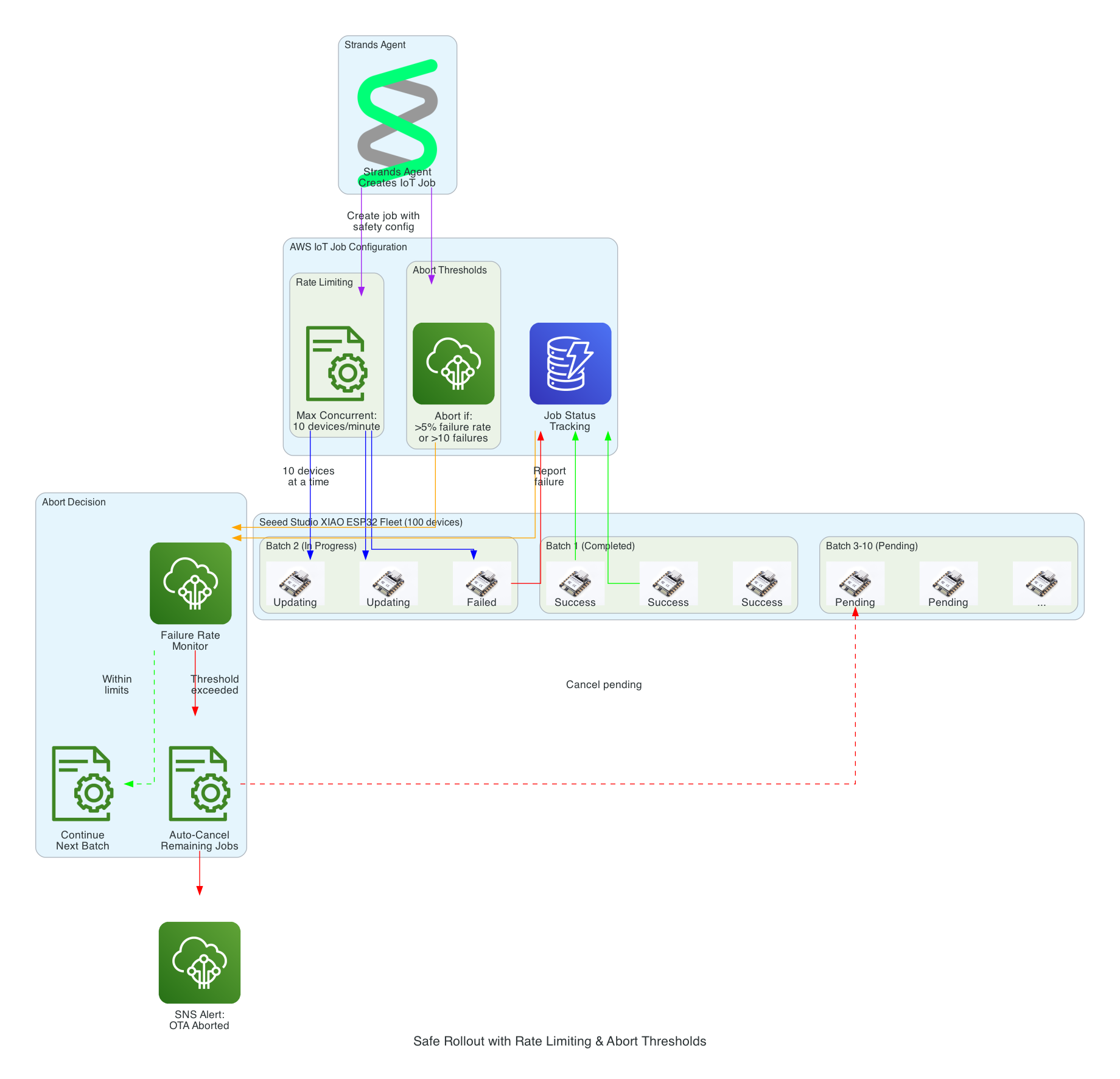
Safe Rollout with Rate Limiting & Abort Thresholds
This diagram illustrates the safety mechanisms that prevent fleet-wide failures during OTA updates by controlling rollout speed and automatically aborting when issues are detected.
Safety Mechanisms:
Rate Limiting - Updates are deployed to a maximum of 10 devices concurrently, preventing network congestion and allowing monitoring
Abort Thresholds - Job automatically cancels if failure rate exceeds 5% or more than 10 absolute failures occur
Batch Processing - Fleet of 100 devices is updated in batches, with completed, in-progress, and pending states tracked
Failure Monitoring - Real-time tracking of success/failure status feeds into abort decision logic
Auto-Cancel - When threshold is exceeded, all pending device updates are automatically cancelled
SNS Alerts - Operators are immediately notified when an OTA rollout is aborted
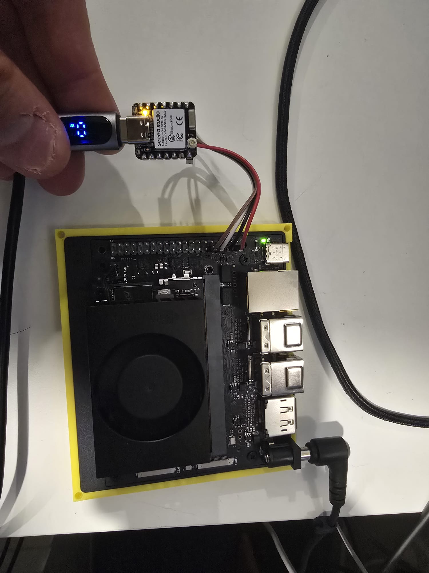
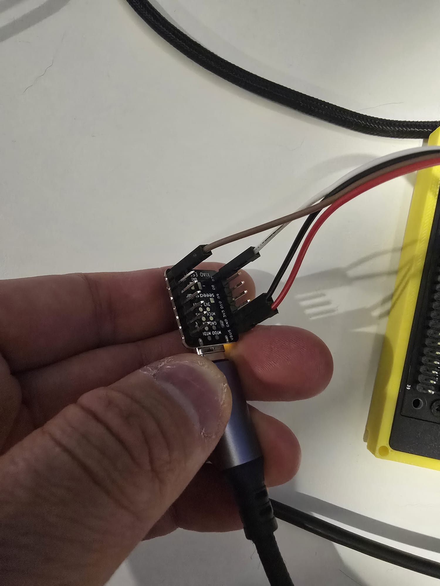
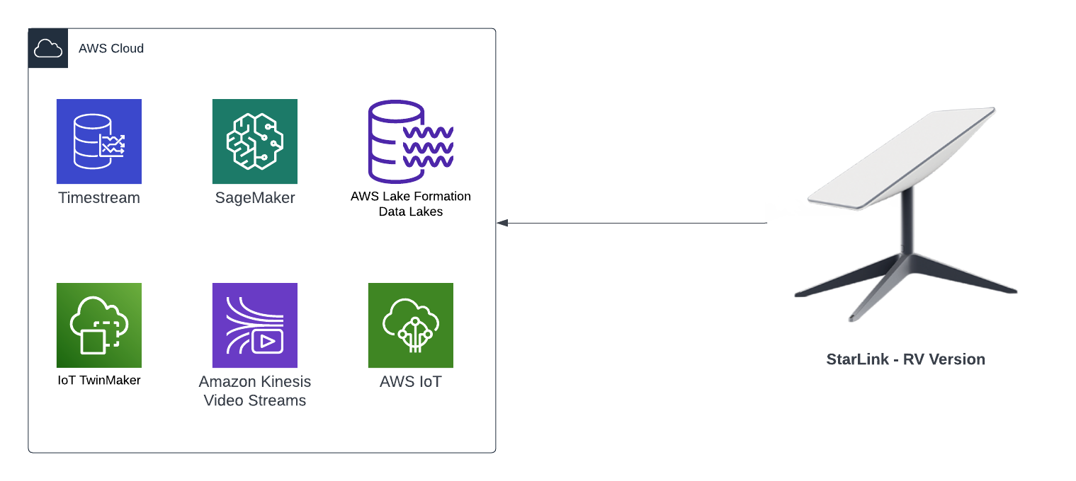
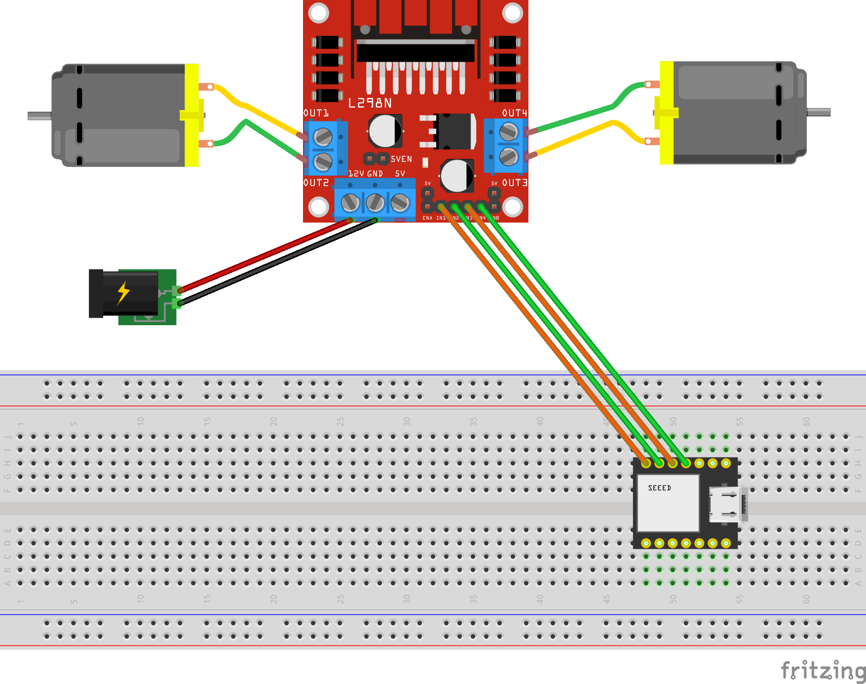
I want to use the Jetson Nano to leverage any sensor readings captured by the ESP32C6 and use it for inferences downstream. In the past I would have tried to send the messages between the devices via AWS IoT Core, but over the wires using UART it is definitely much faster - single digit milliseconds over UART.
Here is the source code to use as a building block to enable a Seeed Studio XIAO ESP32C6 to send messages to a NVIDIA Jetson Nano Super over the UART protocol; uni-direction. The XIAO code is a PlatformIO project and the Jetson Nano Super is a Python script.
These days I am often creating small generic re-usable building blocks that I can pontentially use across new or existing projects, in this blog I talk about the architecture for a LLM based voice chatbot in a web browser built entirely as a serverless based solution.
The key component of this solution is using Amazon Nova 2 Sonic, a speech-to-speech foundation model that can understand spoken audio directly and generate voice responses - all through a single bidirectional stream from the browser directly to Amazon Bedrock, with no backend servers required - no EC2 instances and no Containers.
Goals
Enable real-time voice-to-voice conversations with AI using Amazon Nova 2 Sonic
Direct browser-to-Bedrock communication using bidirectional streaming - no Lambda functions or API Gateway required
Use AWS Amplify Gen 2 for infrastructure-as-code backend definition in TypeScript
Implement secure authentication using Cognito User Pool and Identity Pool for temporary AWS credentials
Handle real-time audio capture, processing, and playback entirely in the browser
Must be a completely serverless solution with automatic scaling
Support click-to-talk interaction model for intuitive user experience
Display live transcripts of both user speech and AI responses
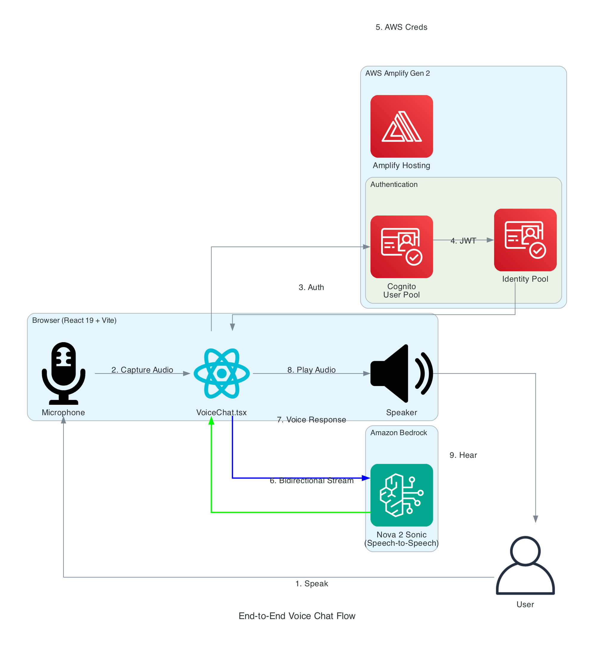
This diagram details the internal architecture of the React application, showing how custom hooks orchestrate audio capture, Bedrock communication, and playback.
Components:
VoiceChat.tsx - Main UI component that coordinates all hooks and renders the interface
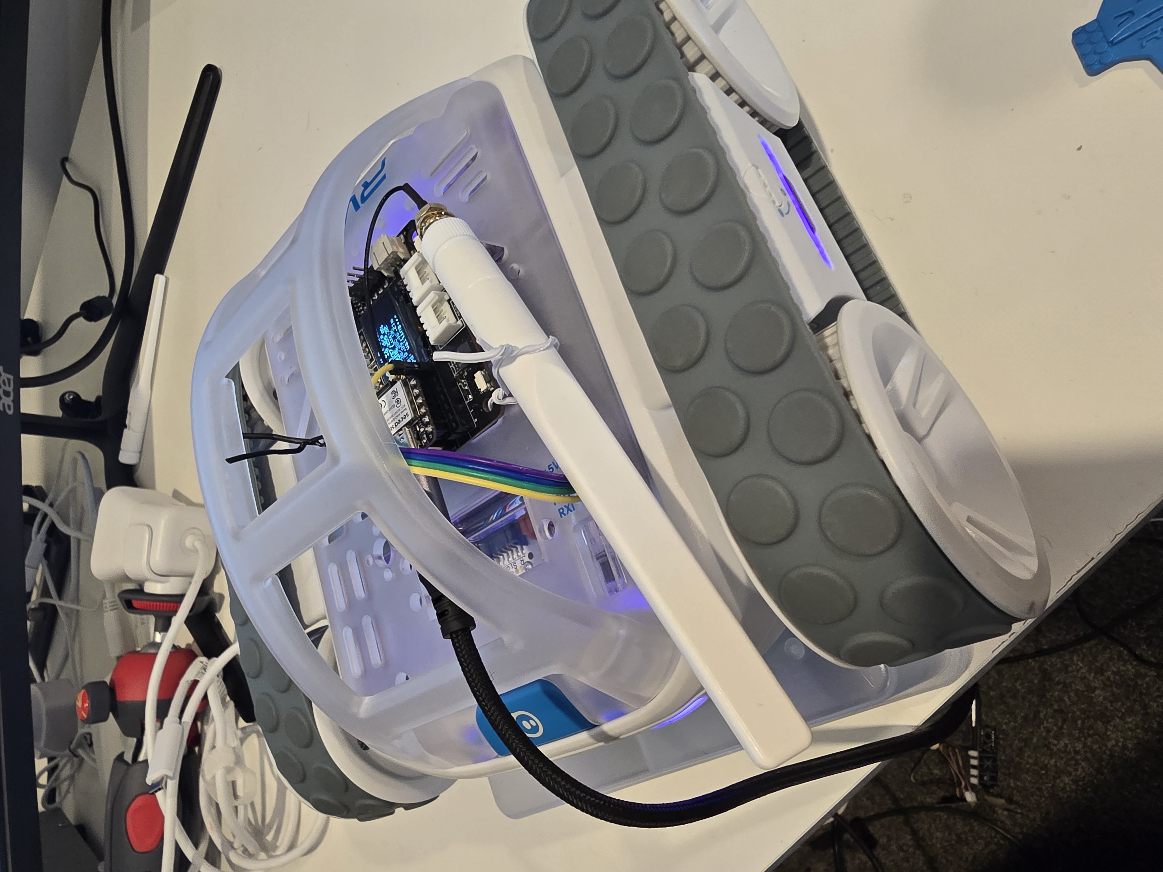
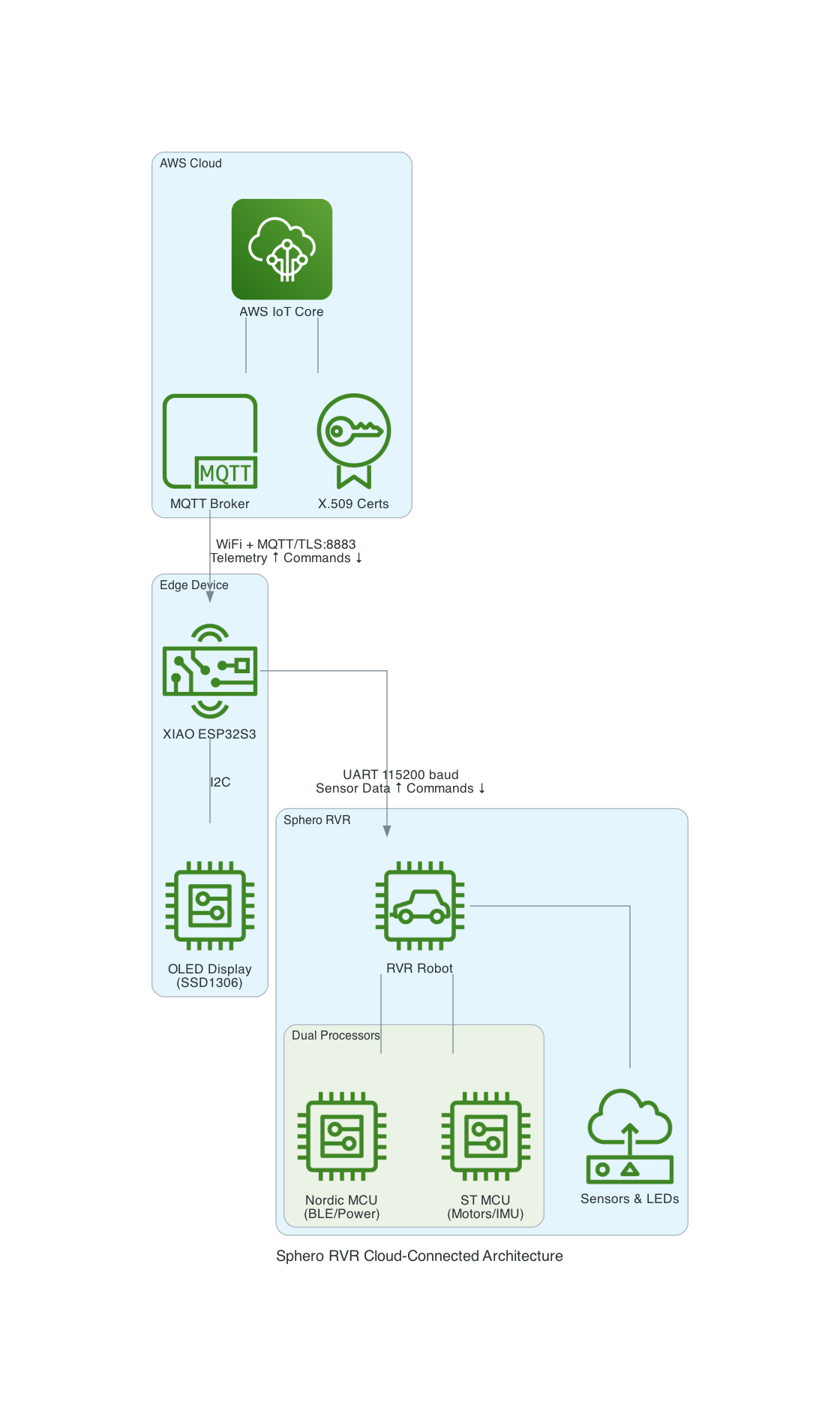
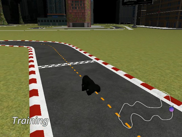
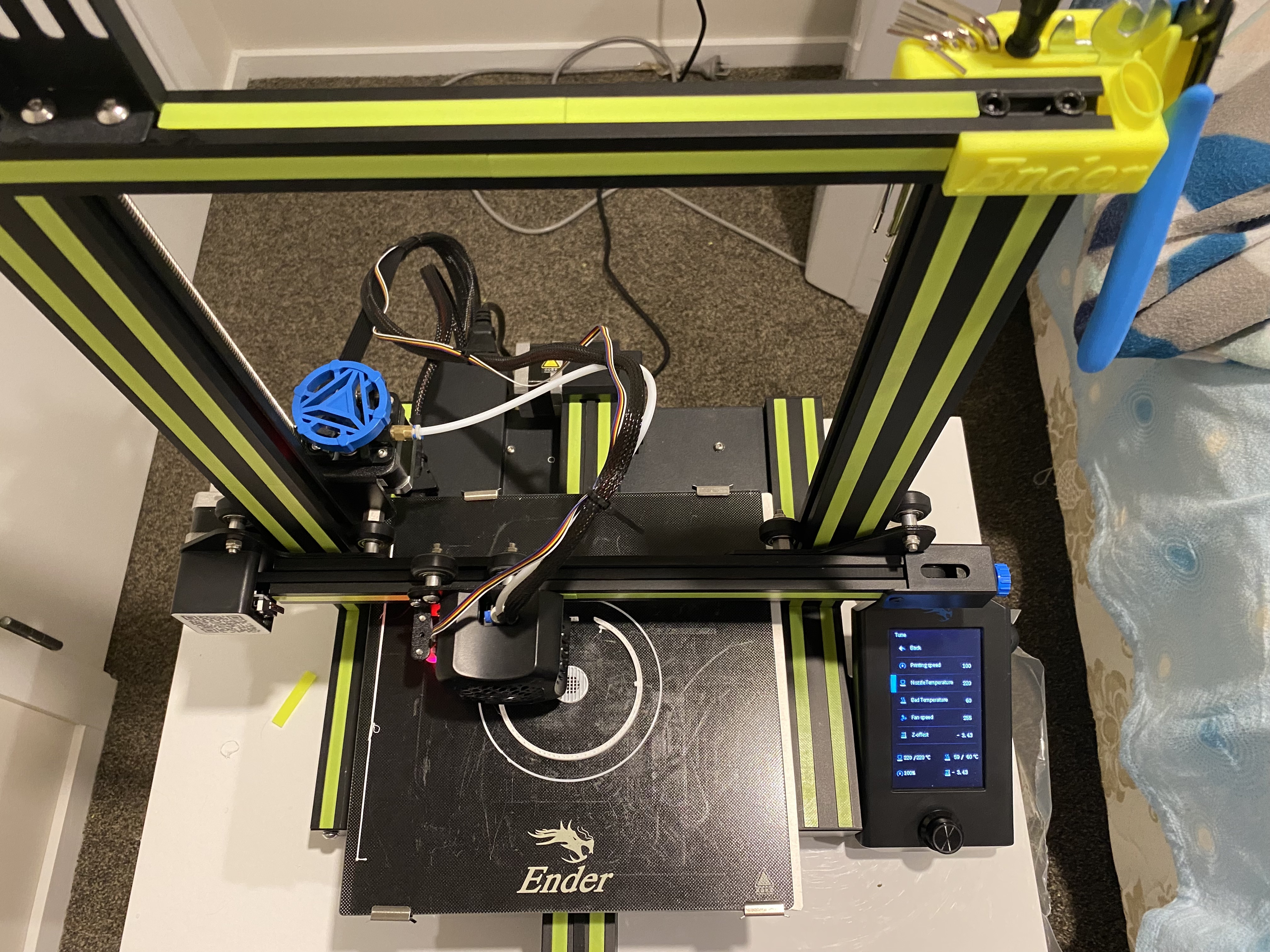
A Sphero RVR integrated with a Seeed Studio XIAO ESP32S3 with telemetry uploaded into, and also, basic drive remote control commands received from any where leveraging AWS IoT Core.
Lately I have been aiming to go deep on AI Robotics, and last year I have been slowly experimenting more and more with anything that is AI, IoT and Robotics related; with the intention of learning and going as wide and as deep as possible in any pillars I can think of. You can check out my blogs under the Robotics Project to see what I have been up to. This year I want to focus on enabling mobility for my experiments - as in providing wheels for solutions to move around the house, ideally autonomously; starting off with wheel based solutions bought off-shelve, followed by solutions that I build myself from open-sourced projects people have kindly contirbuted online, and then ambitiously designed, 3D Printed and built all from the ground up - perhaps in a couple of years time.
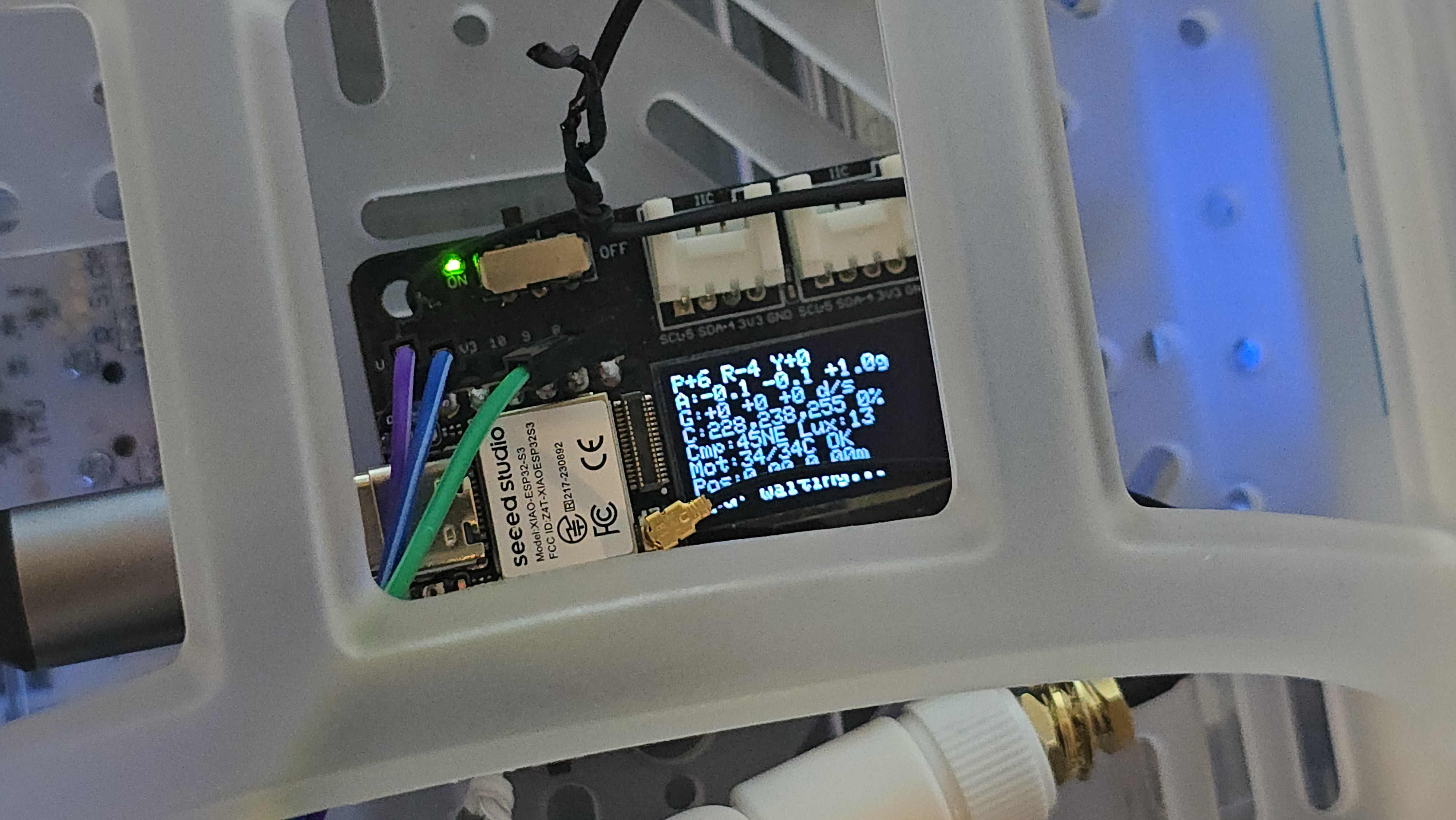
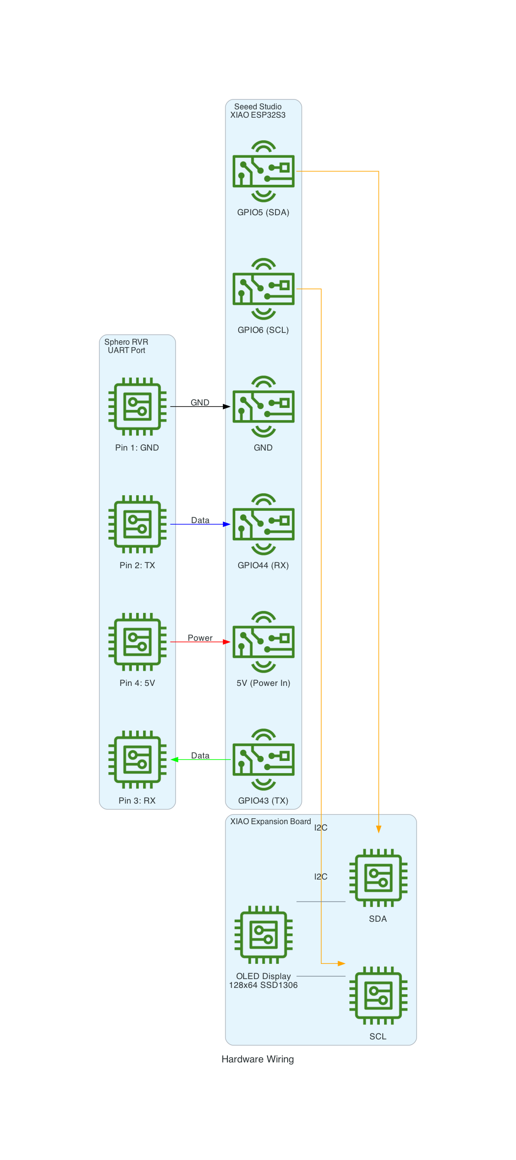
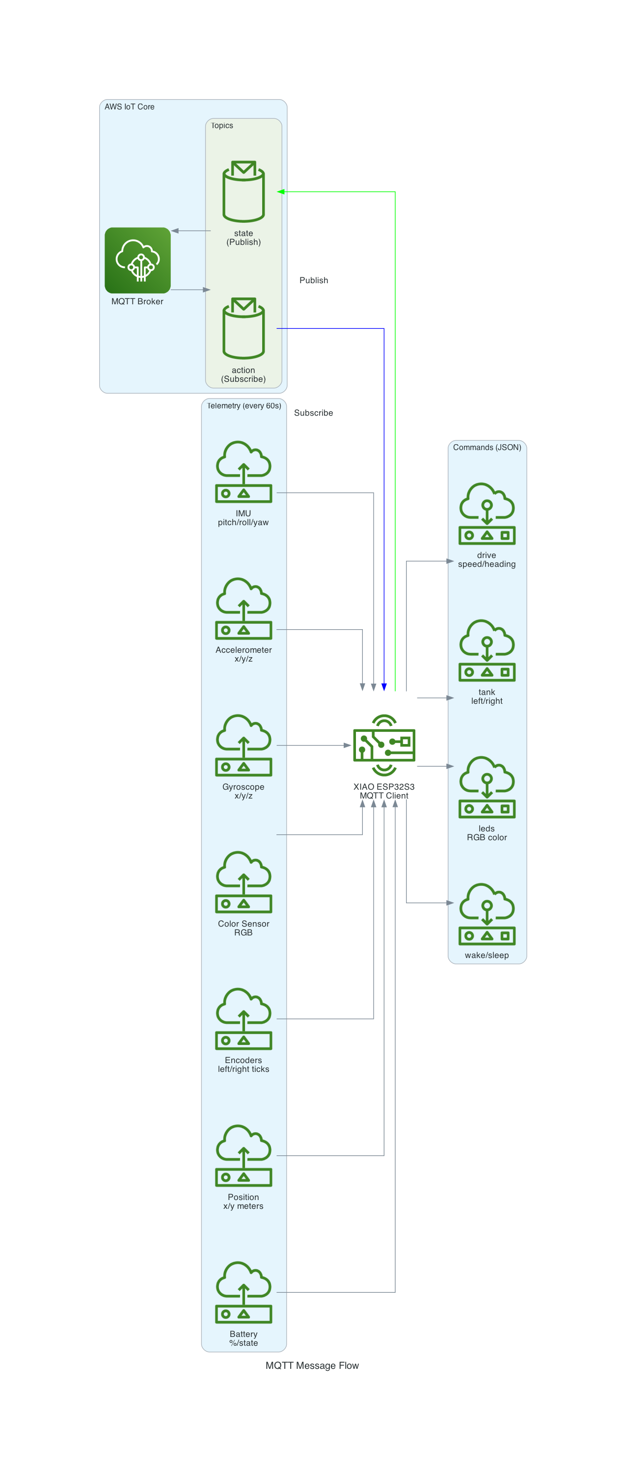
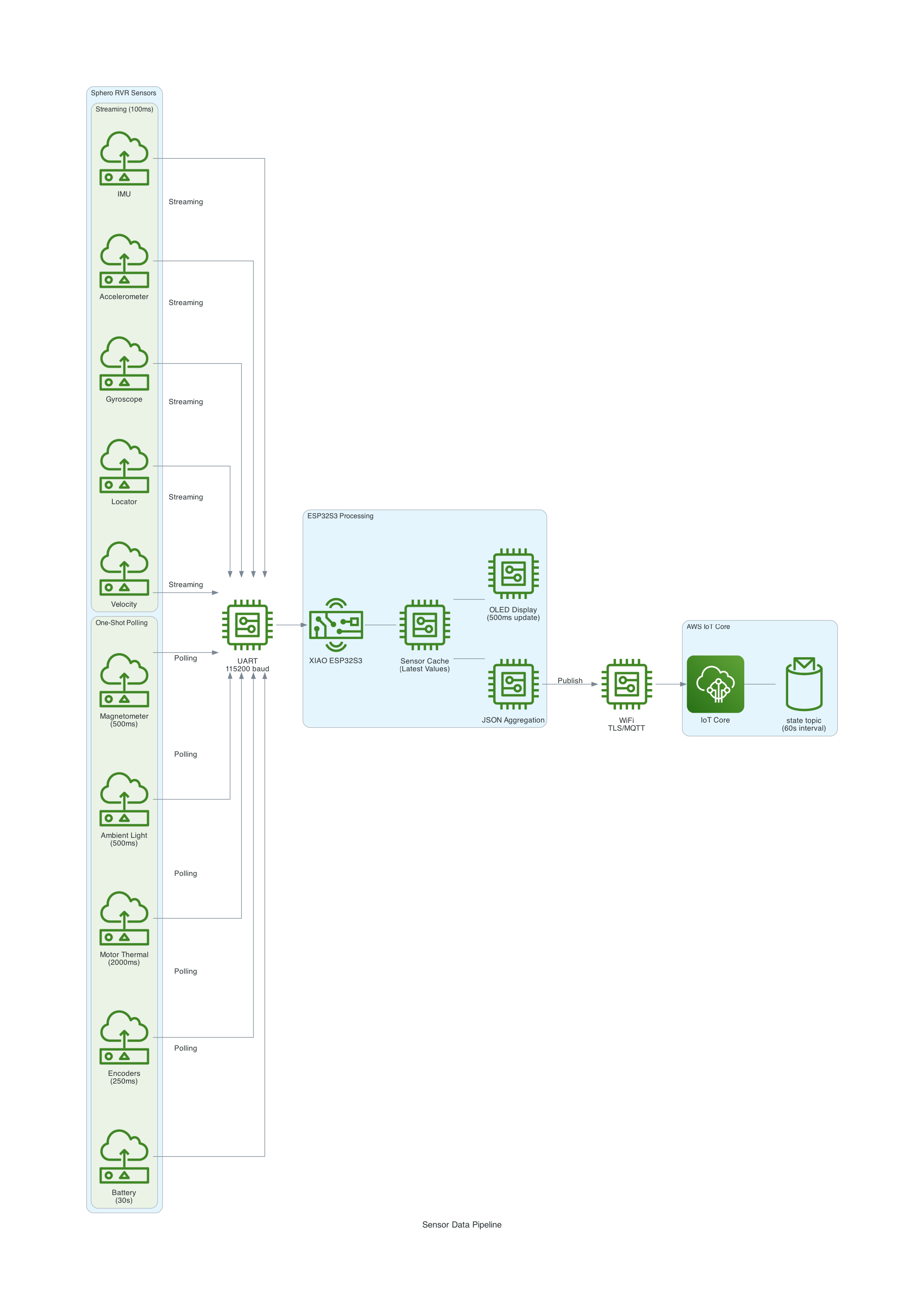
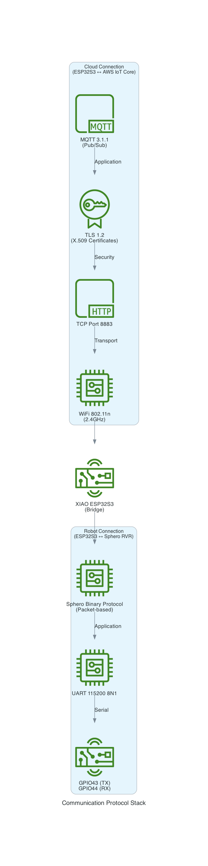
This project uses a Seeed Studio XIAO ESP32S3 microcontroller to communicate with a Sphero RVR robot via UART, while simultaneously connecting to AWS IoT Core over WiFi. The system publishes real-time sensor telemetry and accepts remote drive commands through MQTT.
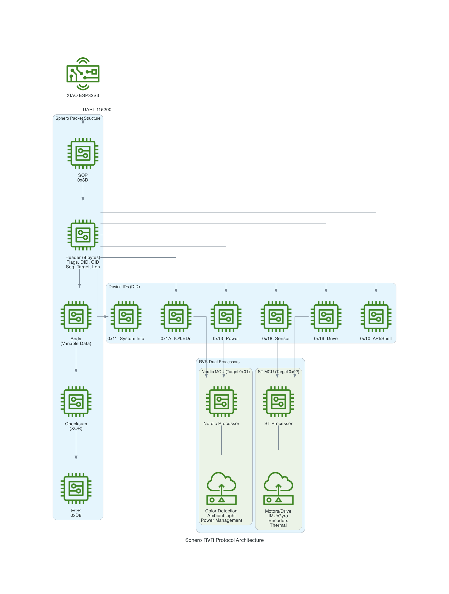
The Sphero RVR uses a binary packet-based protocol over UART. Each packet contains a start-of-packet byte (0x8D), an 8-byte header with device ID and command ID, variable-length data body, checksum, and end-of-packet byte (0xD8). The RVR has two internal processors: Nordic (handles BLE, power, color detection) and ST (handles motors, IMU, encoders).
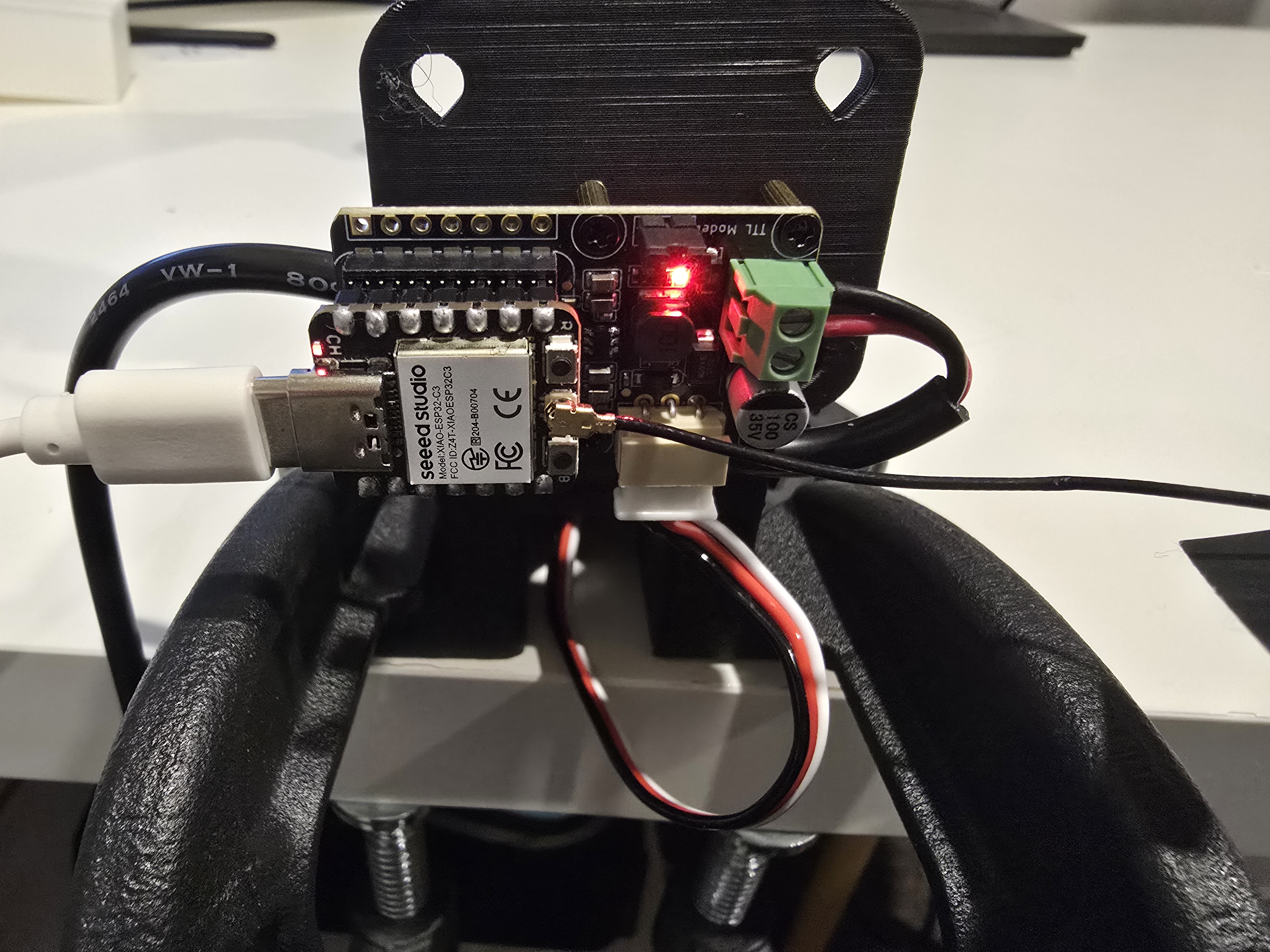
The LeRobot Follower arm is subscribed to an IoT Topic that is being published in real-time by the LeRobot Leader arm over AWS IoT Core, using a Seeed Studio XIAO ESP32C3 integrated with a Seeed Studio Bus Servo Driver Board, the driver board is controlling the 6 Feetech 3215 Servos over the UART protocol.
In this video I demonstrate how to control a set of Hugging Face SO-101 arms over AWS IoT Core, without the use of the LeRobot framework, nor using a device such as a Mac nor a device like Nvidia Jetson Orin Nano Super Developer Kit. Only using Seeed Studio XIAO ESP32C3 and AWS IoT.
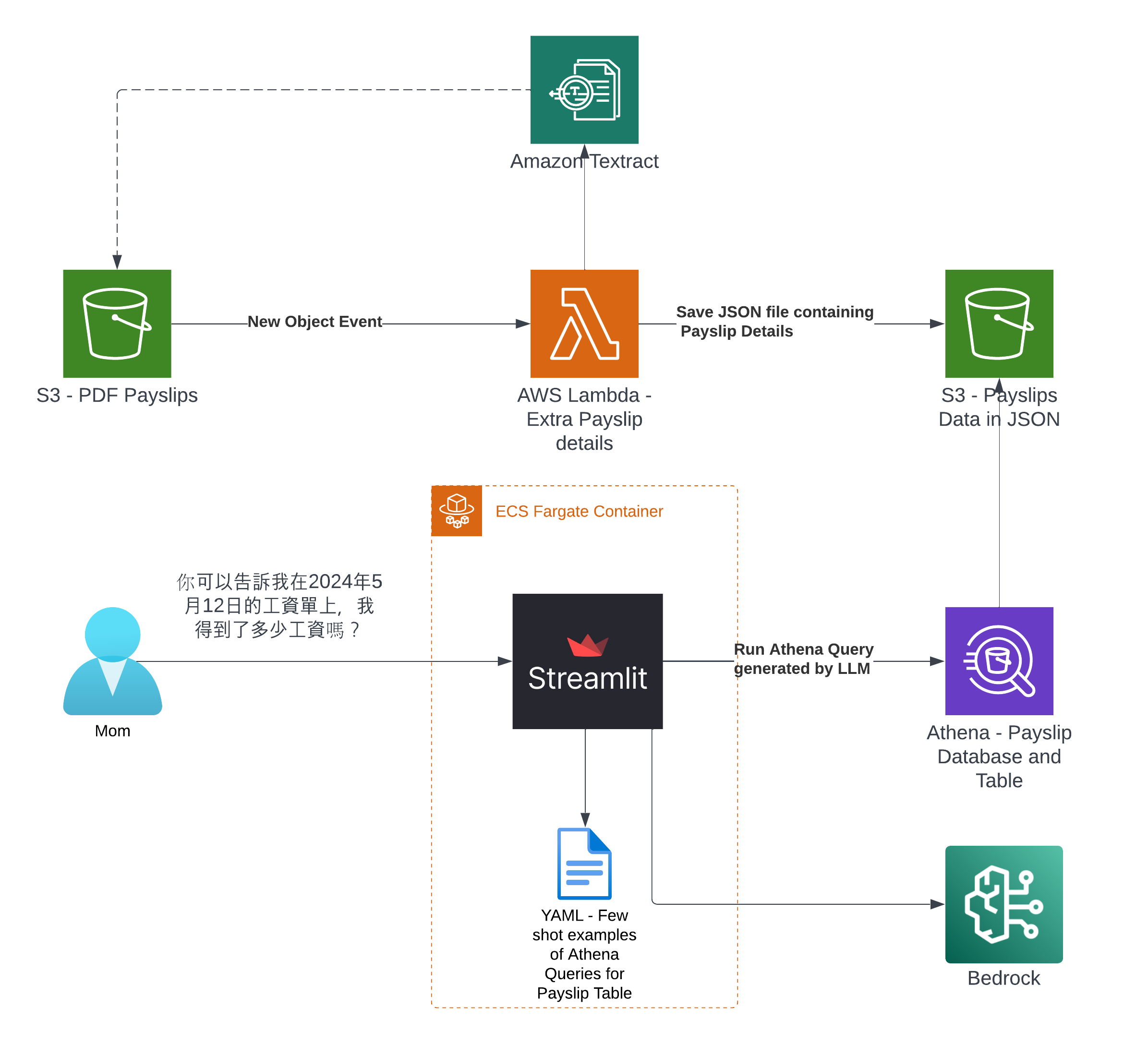
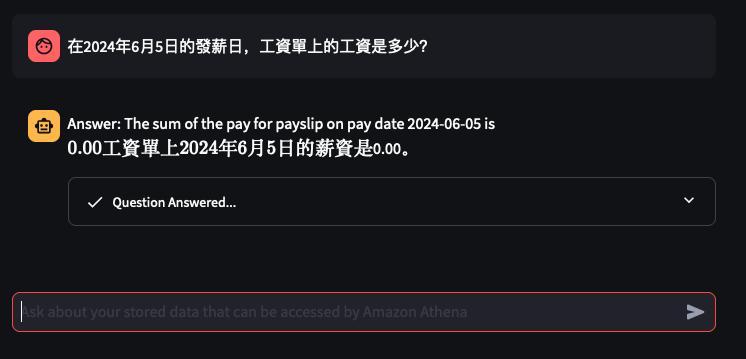
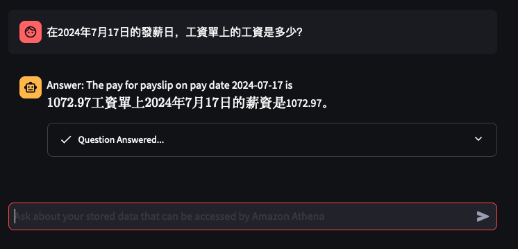
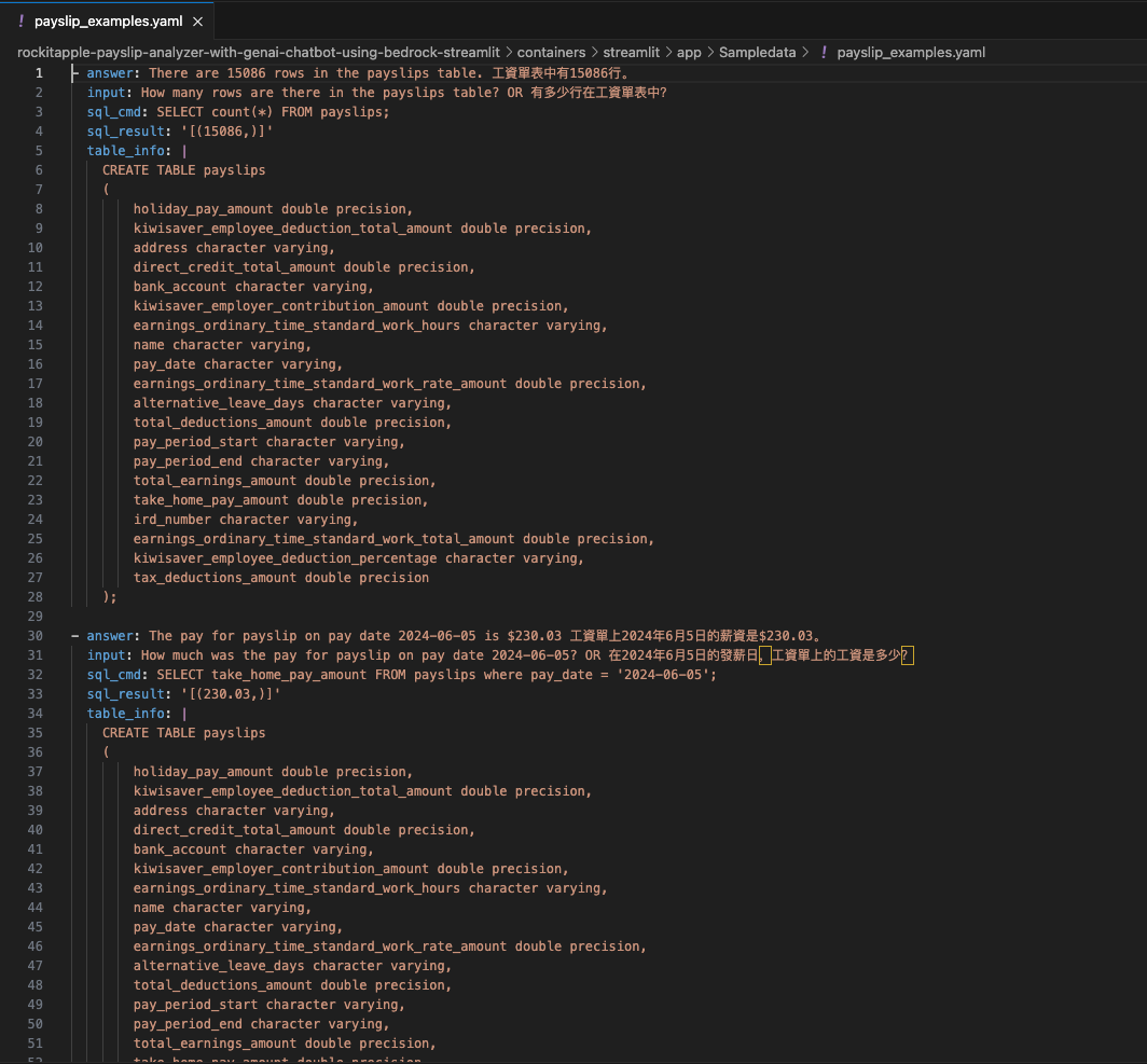
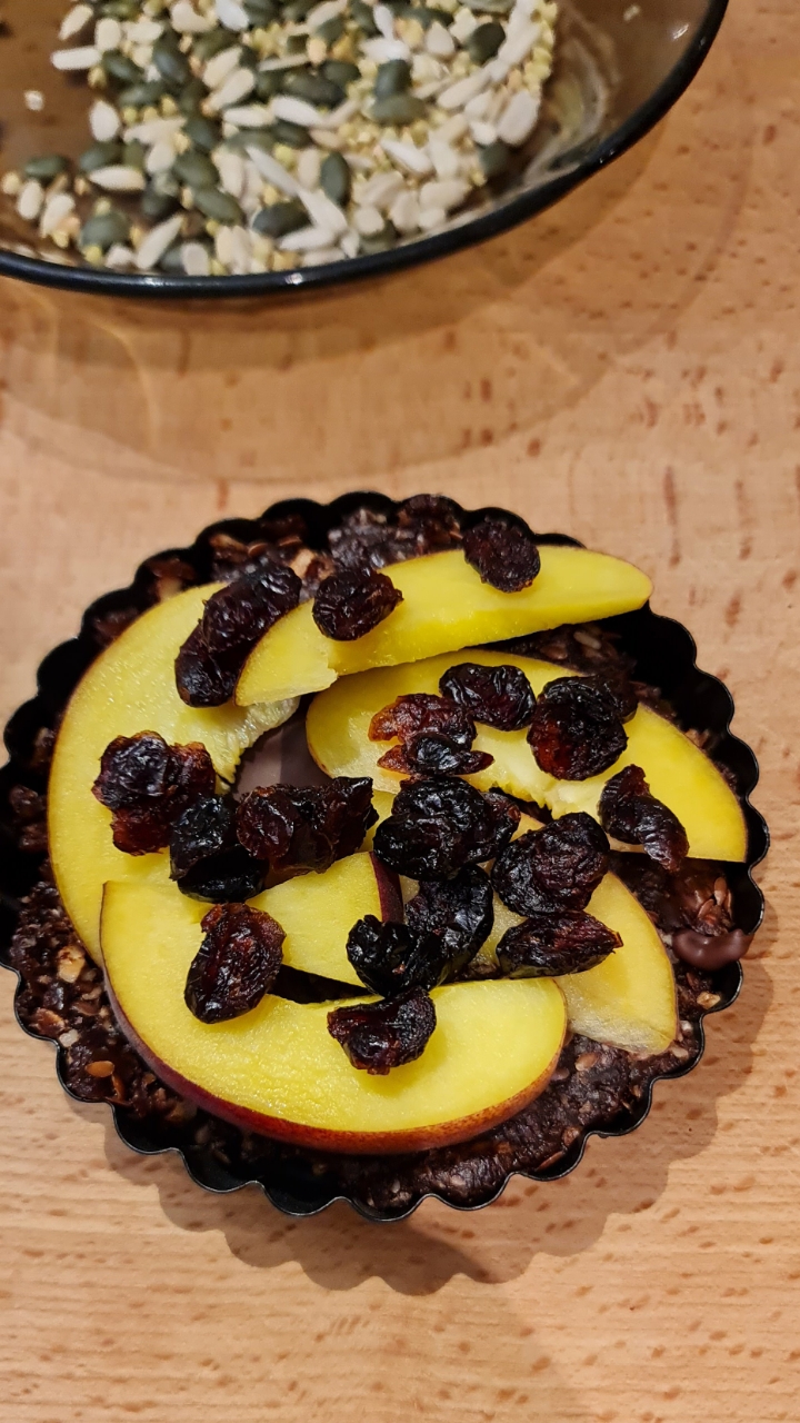
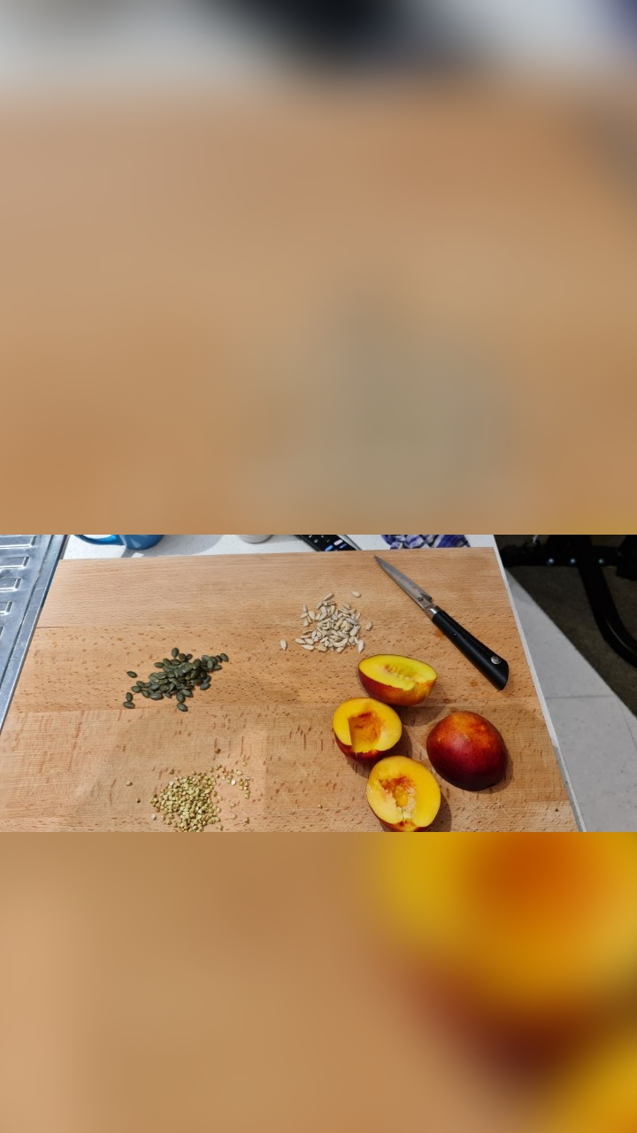
It's the time of year where I normally have to start doing taxes, not for myself but for my parents. Mum works at various fruit picking / packing places in Hawkes Bay throughout the year, so that means there are all sorts of Payslips from different employers for the last financial year. Occasionally mum would ask me specific details about her weekly payslips, and that usually means: download a PDF from and email -> open up the PDF -> find what's she asking for -> look at the PDF -> can't find it so ask what mum meant -> find the answer -> explain it to her.
Solution & Goal
The usual format,challenge: create a Generative AI conversational chat to enable mum to ask in her natural language specific details of,
And the goal: outsource the work to AI = more time to play. :-)
Success Criterias
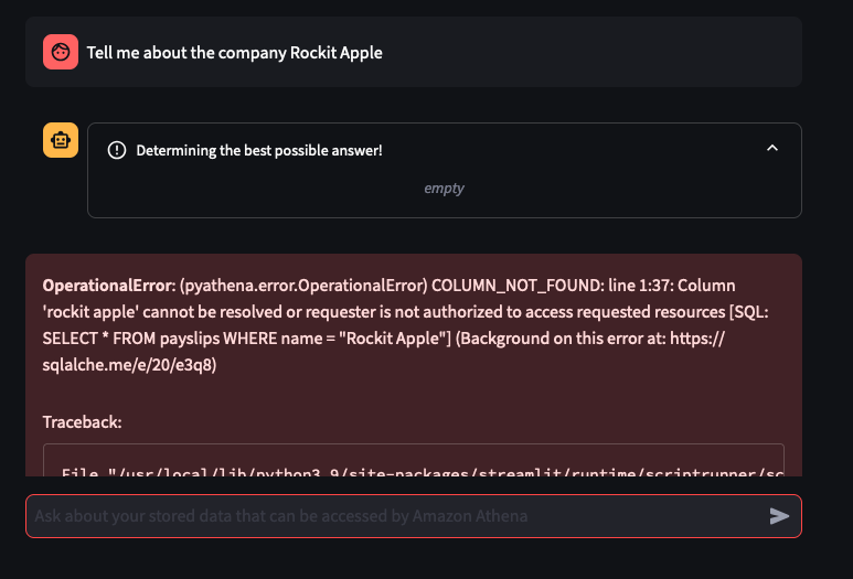
Automatically extract details from Payslips - I've only tested it on Payslips from Rockit Apple.
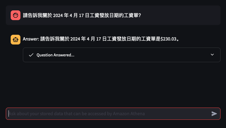
Enable end-user to ask in Cantonese details of a Payslip
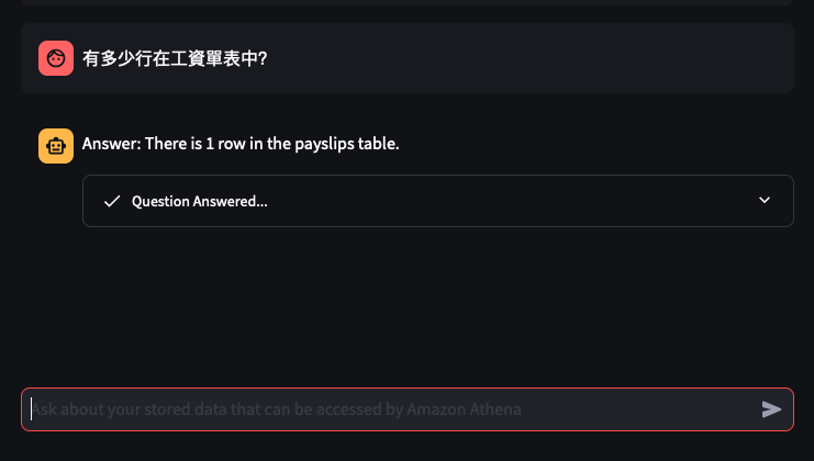
Retrieve data from an Athena Table where the
Create a Chatbot to receive question in Cantonese around the user's Payslips stored in the Athena Table, and generate a response back to the user in Cantonese
So what's the Architecture?
Note
I've only tried it for Payslips generated by this employer: Rockit Apple
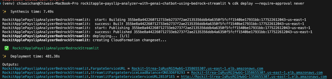
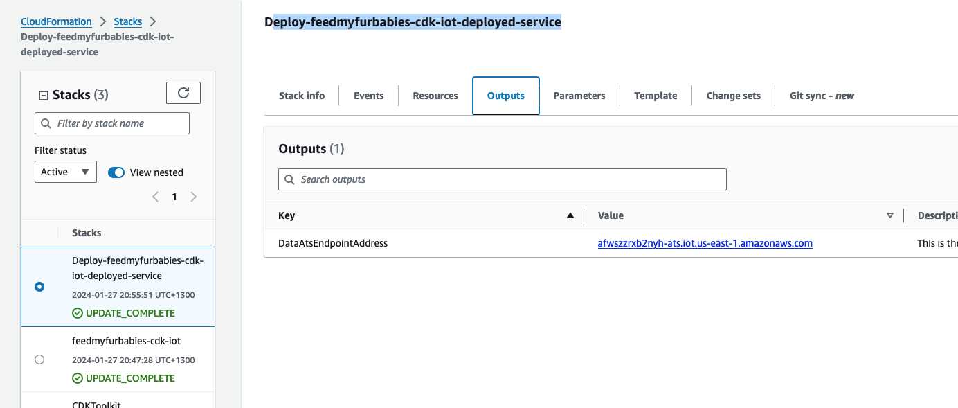
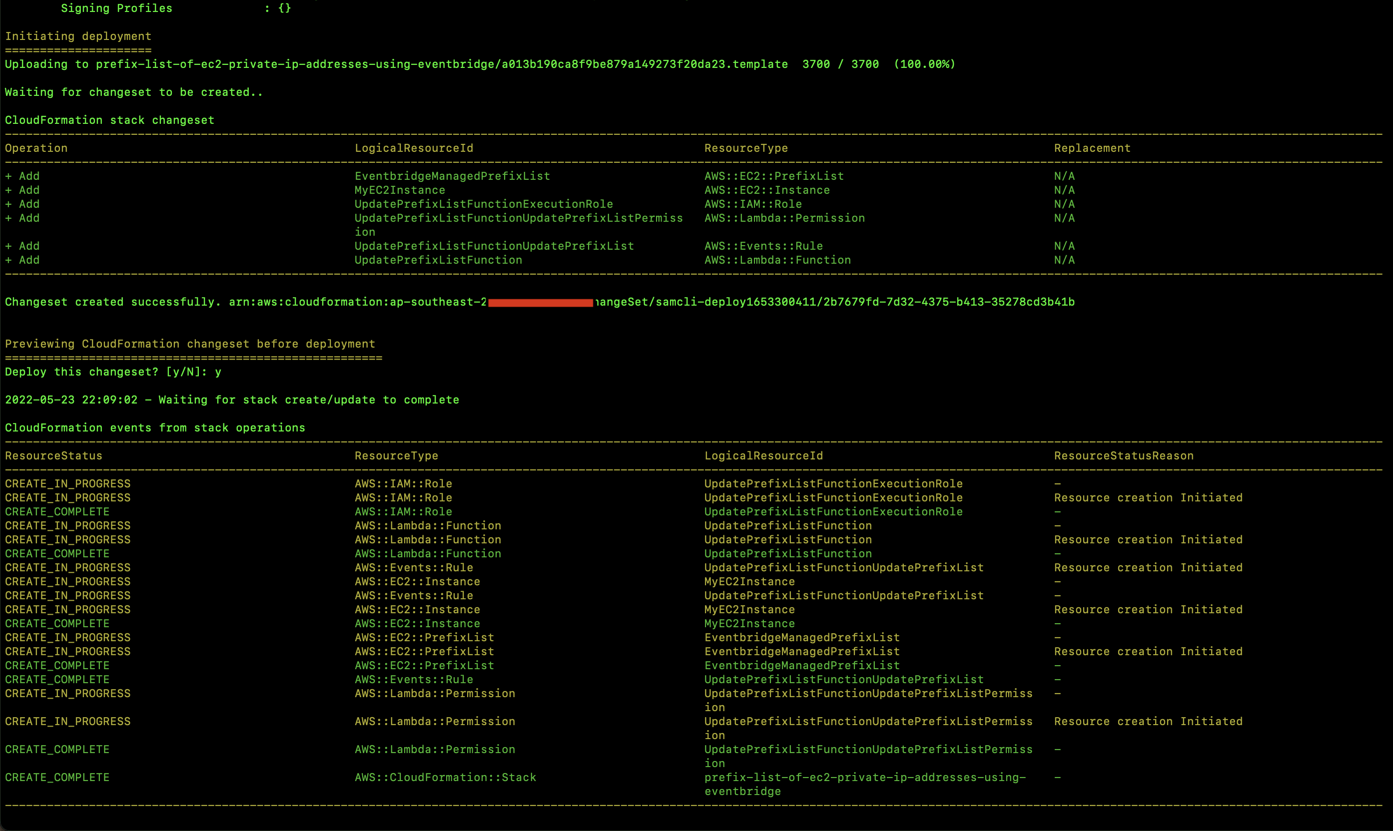
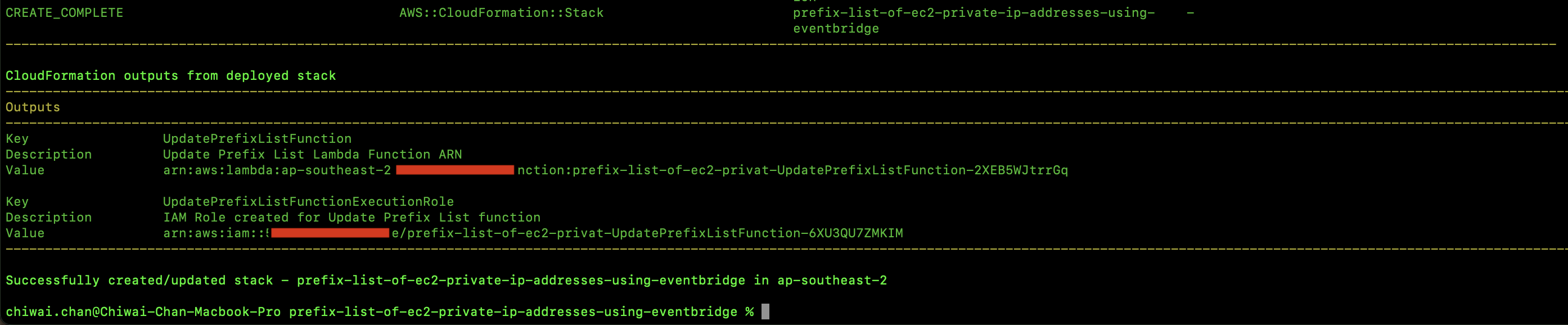
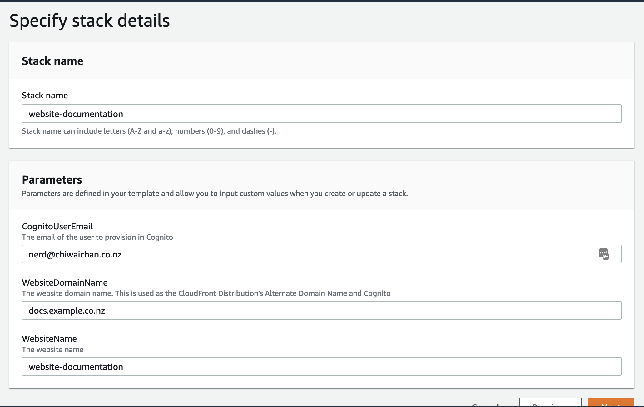
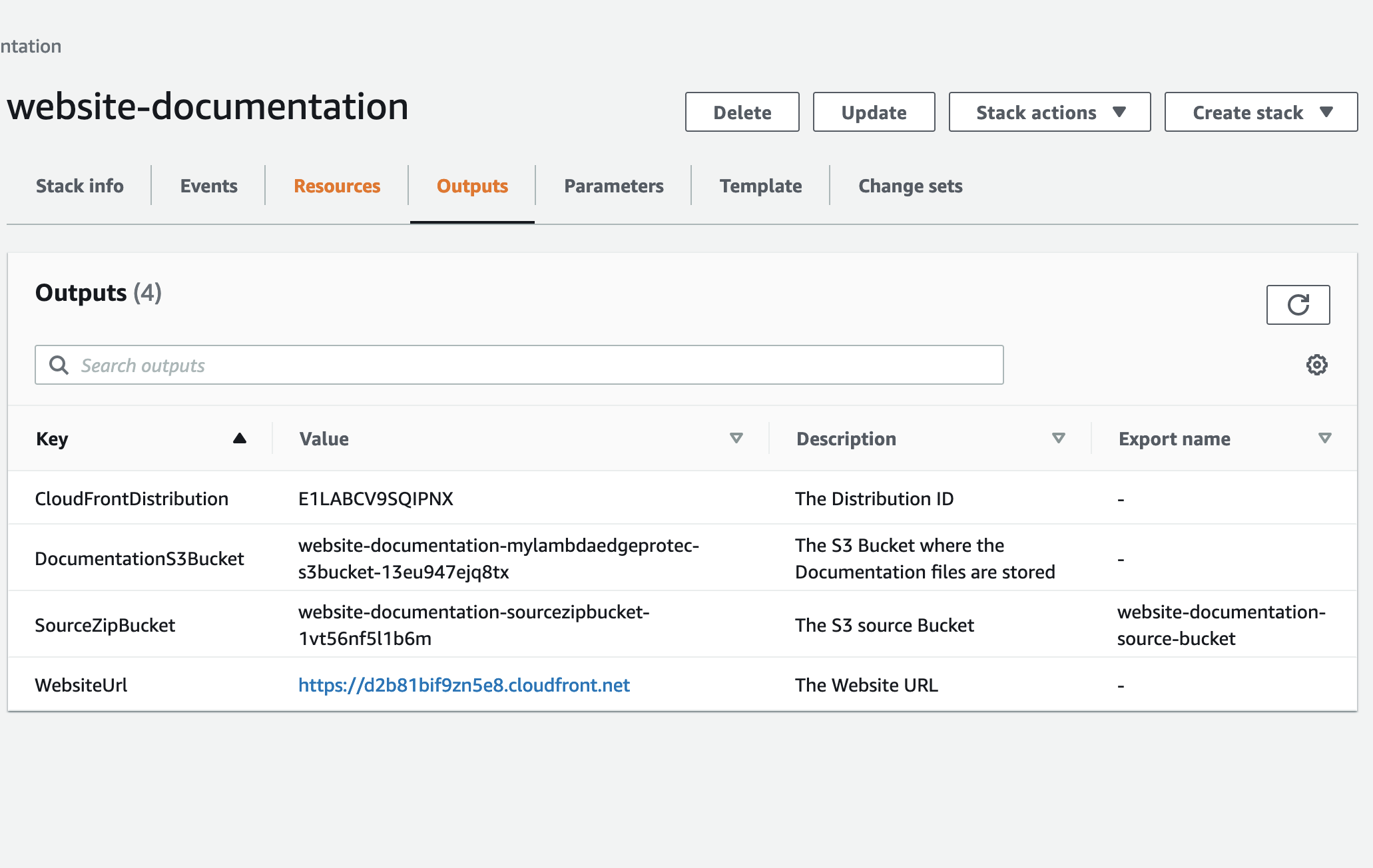
You should see this as a result of calling the cdk deploy command
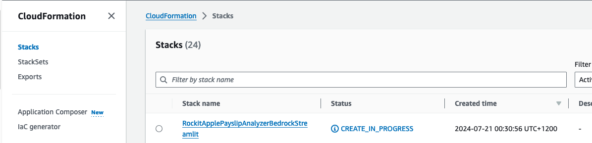
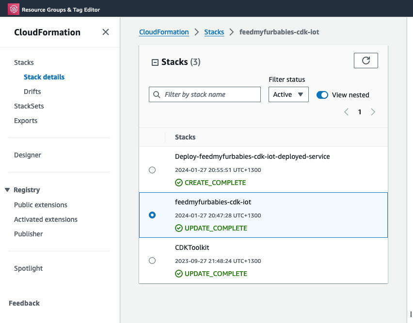
Check that the CloudFormation Stack is being created in the AWS Console
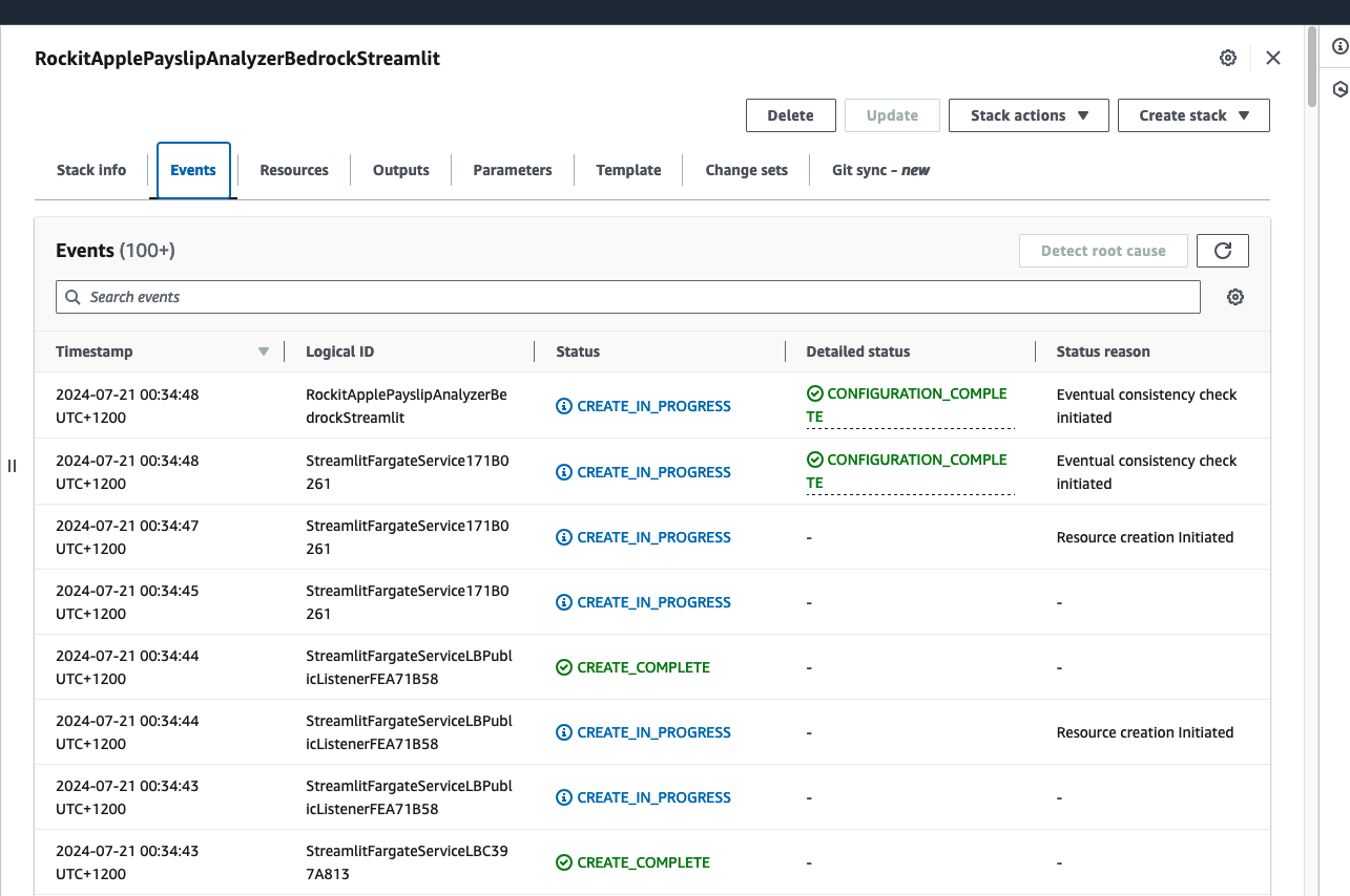
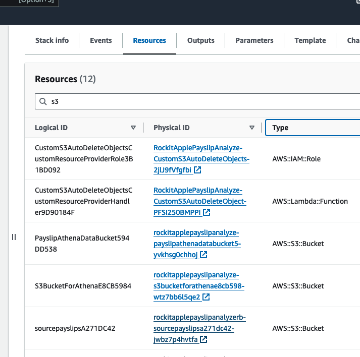
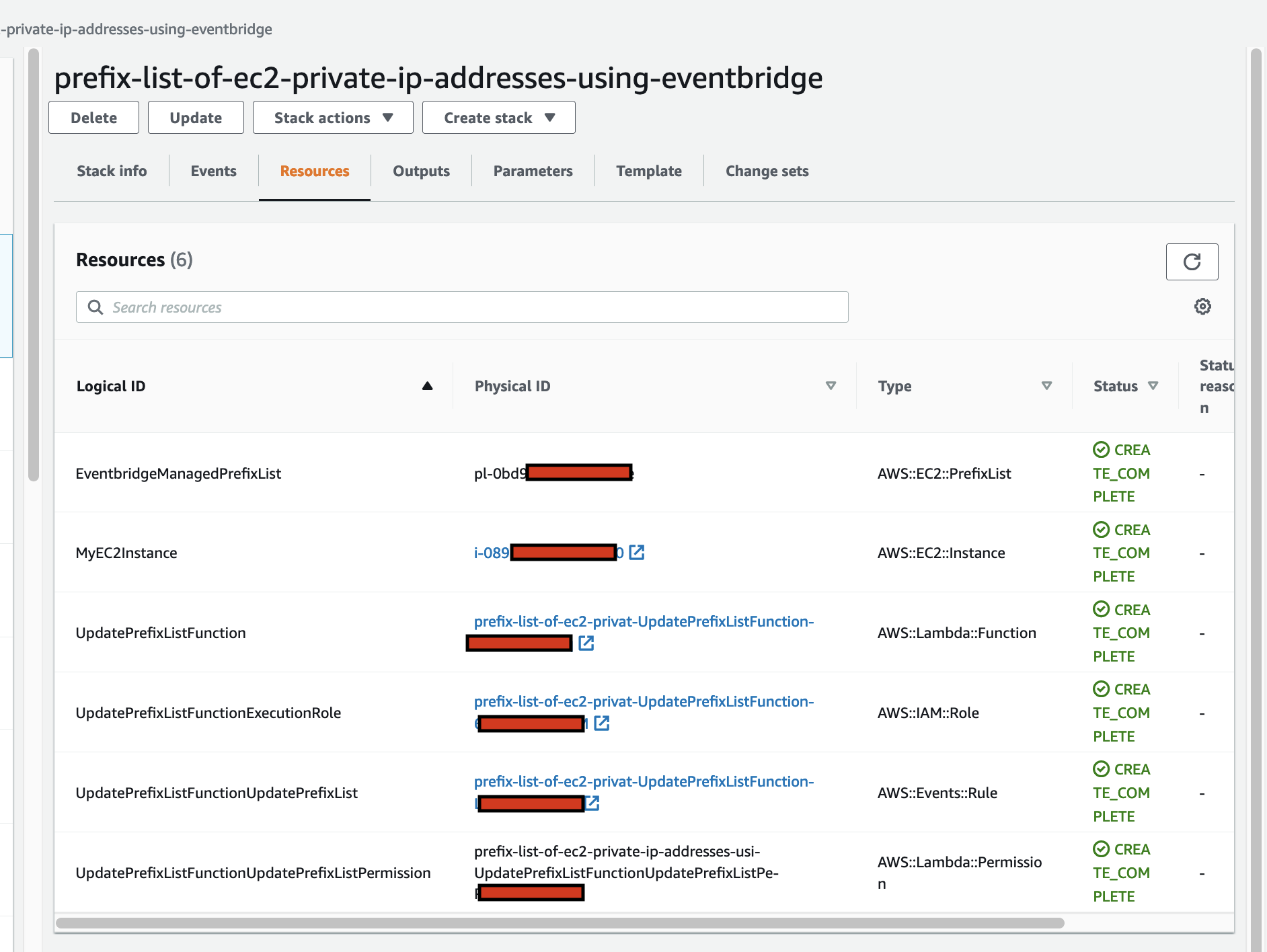
Click on it to see the Events, Resources and Output for the Stack
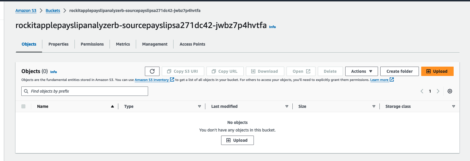
Find the link to the S3 Bucket to upload Payslip PDFs into, in the Stack's Resources, find the S3 Bucket with a with a Logical ID that starts with "sourcepayslips" and click on its Physical ID link.
Upload your PDF Payslips into here
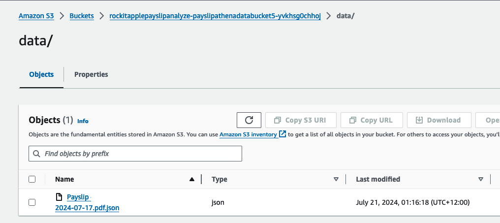
Find the link to the S3 Bucket where the extracted Data will be stored into for the Athena Table, in the Stack's Resources, find the S3 Bucket with a with a Logical ID that starts with "PayslipAthenaDataBucket" and click on its Physical ID link.
There you can find a JSON file, it should take about a few minutes to appear after you upload the PDF.
It was created by the Lambda shown in the architecture diagram we saw earlier, it uses Amazon Textract to extract the data from each Paylip using OCR, using the Queries based feature to extract the Text from a PDF by enabling us to use queries in natural language to configure what we want to extract out from a PDF.
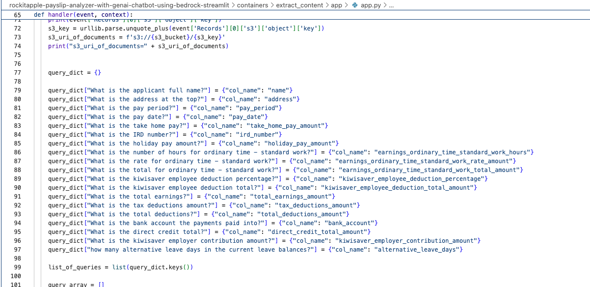
Find the "app.py" file shown in the folder structure in the screenshot below, you can modify the wording of the Questions the Lambda function uses to extract the details from the Payslip, to suit the specific needs based on the wording of your Payslip; the result of each Question extracted is saved to the Athena table using the column name shown next to the Question.
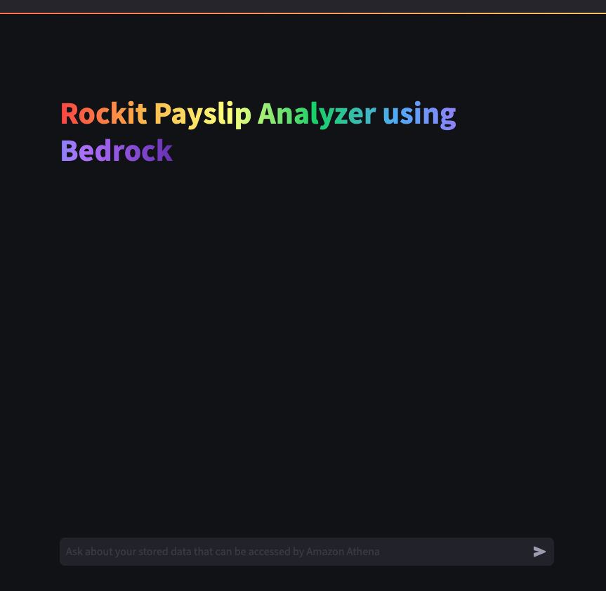
What it looks like in action
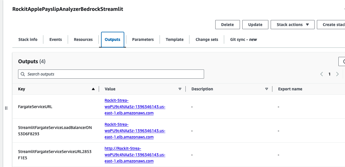
Go to the CloudFormation Stack's Outputs to get the URL to open the Streamlit Application's frontend.
Click the value for the Key "StreamlitFargateServiceServiceURL"
That will take you to a Streamlit App hosted in the Fargate Container shown in the architecture diagram
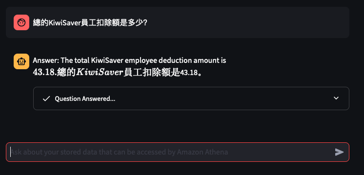
Lets try out some examples
Things don't always go well
You can tweak the Athena Queries generated by the LLM by providing specific examples tailoured to your Athena Table and its column names and values - known as a Few-Shot Learning. Modify this file to tweak the Queries feed into the Few-shot examples used by Bedrock and the Streamlit app.
I based my app on the example for Athena, I wrapped the Streamlit app into a Fargate Container and added Textract to extract Payslips details from PDFs and this app was the output of that.
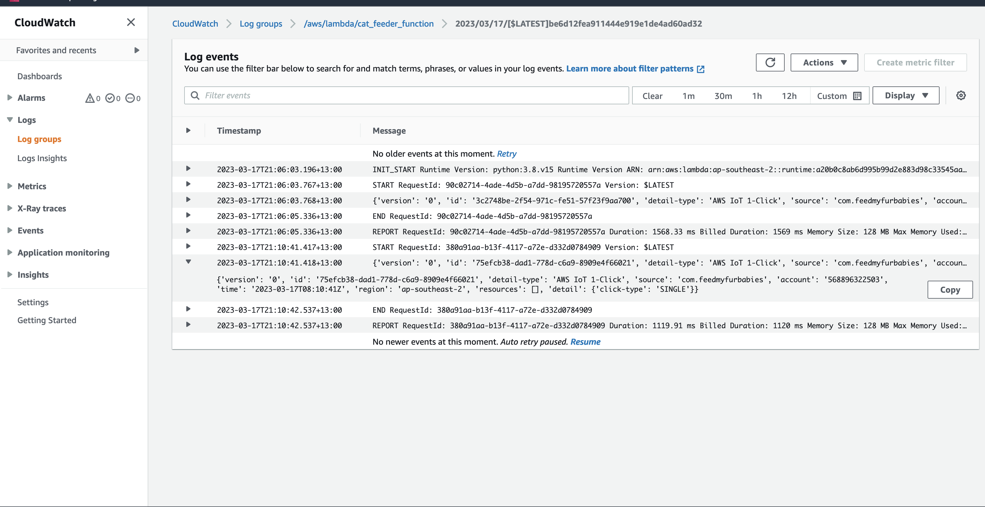
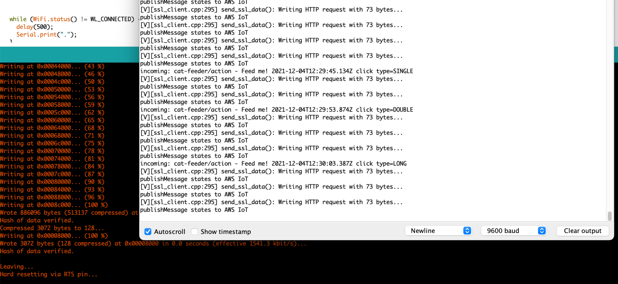
In my code examples I shared in the past, when I sent and received IoT messages and states to and from AWS Core IoT Topics, I only implemented subscribers to react to perform a functionality when an MQTT message is received on a Topic; while that it was useful when my FurBaby was feed in the case when the Cat Feeder was triggered to drop Temptations into the bowls, however, we did
not keep a record of the feeds or the State of the Cat Feeder into some form of data store over time - this meant we did not track when or how many times food was dropped into a bowl.
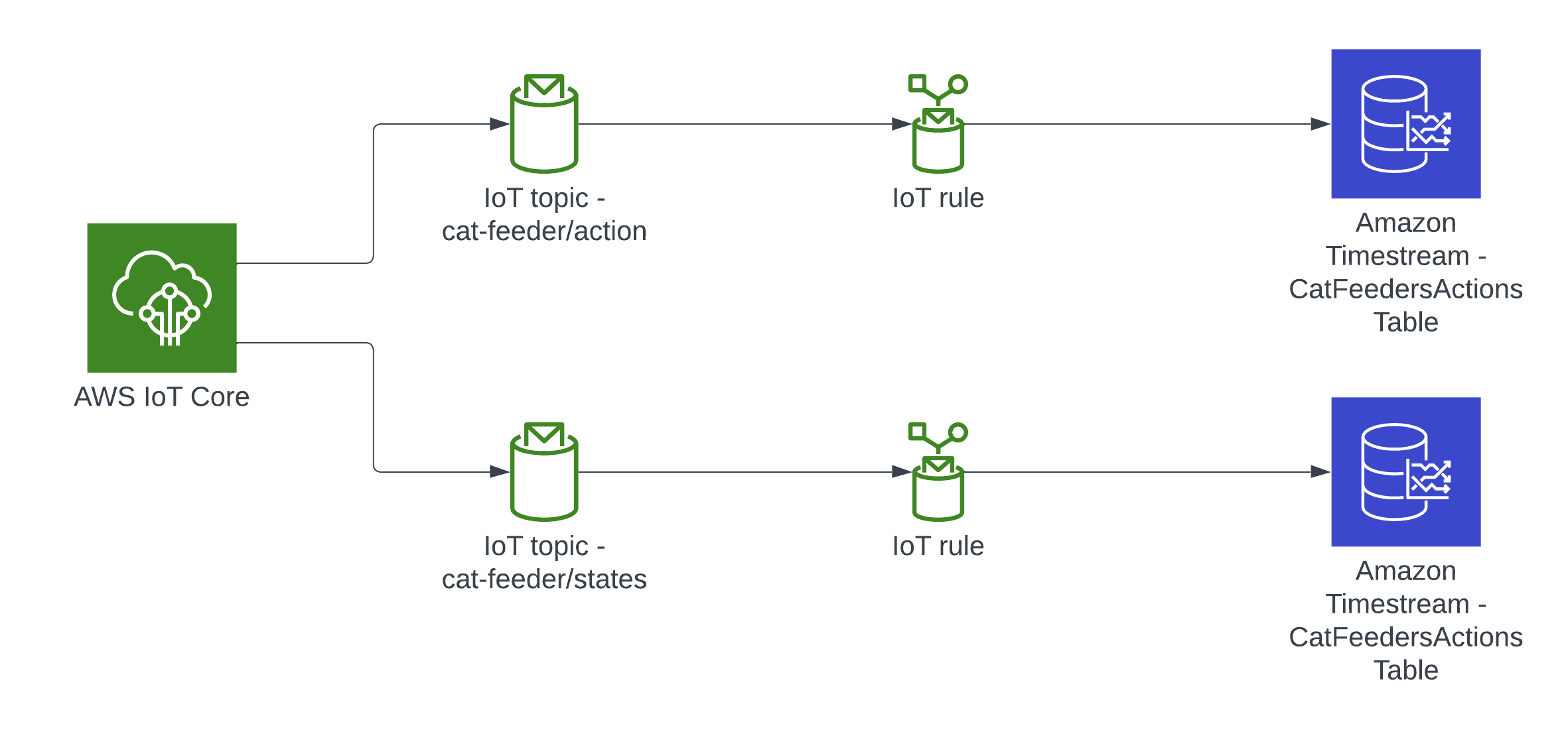
In this blog, I will demonstrate how to store the data in the MQTT messages sent to AWS IoT Core and ingest the data into Amazon Timestream database; Timestream is a serverless time-series database that is fully managed so we can leverage with worrying about maintaining the database infrastructure.
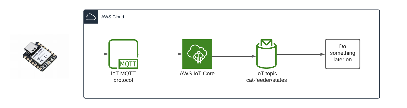
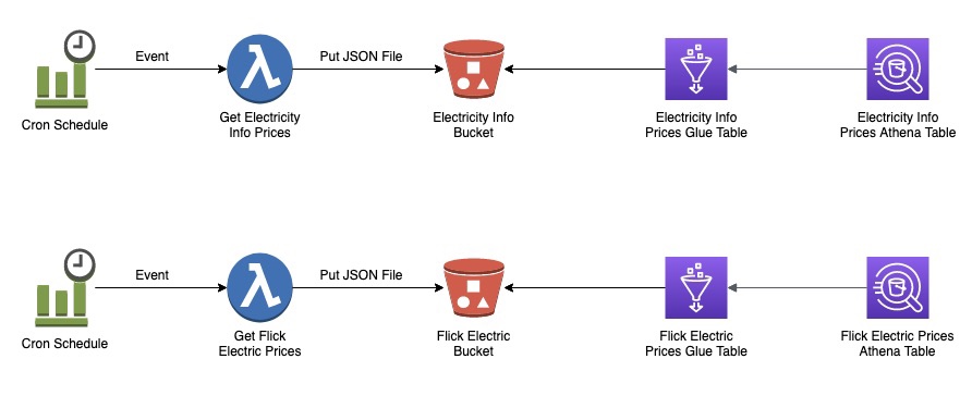
Architecture
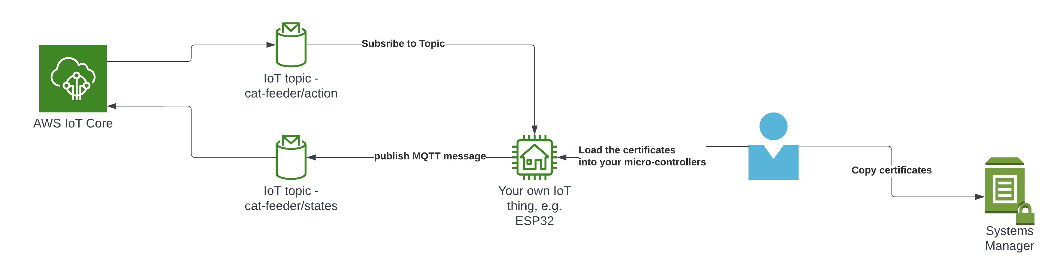
In this architecture we have two AWS IoT Core Topics, where each IoT Topic has an IoT Rule associated with it that will send all the data from every MQTT message receieved from that Topic - there is an ability to filter the messages but we've not using to use it, and that data is ingested into a corresponding Amazon Timestream table.
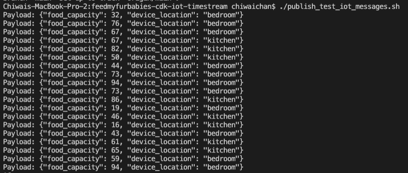
Simulate an IoT Thing to Publish MQTT Messages to IoT Core Topic
In the root directory of the repository is a script that simulates an IoT Thing and it will constantly publish MQTT messages to the "cat-feeder/states" Topic; ensure you have the AWS CLI installed on your machine with a default profile as it relies on it, and ensure the Access Keys used by the default profile has the permission to call "iot:Publish".
It sends a random number for the "food_capacity" that ranges 0-100 to represent the percentage of food that is remaining in a cat feeder, and a values for the "device_location" as we are scaling out with the number of cat feeders placed around the house. Be sure to send the same JSON structure in your MQTT message if you decide to not use the provided script to send the messages to the Topic.
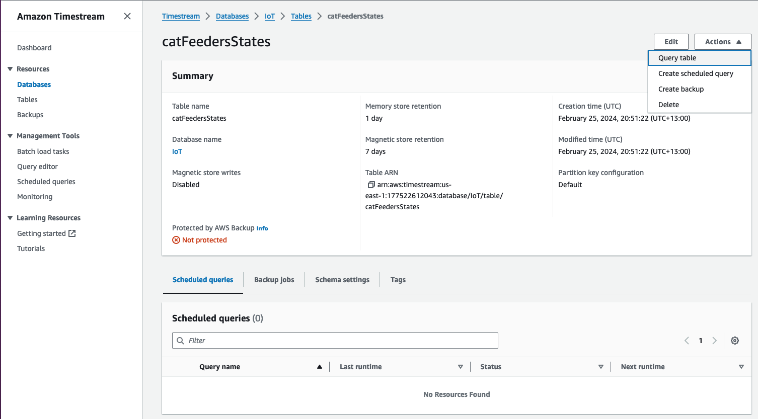
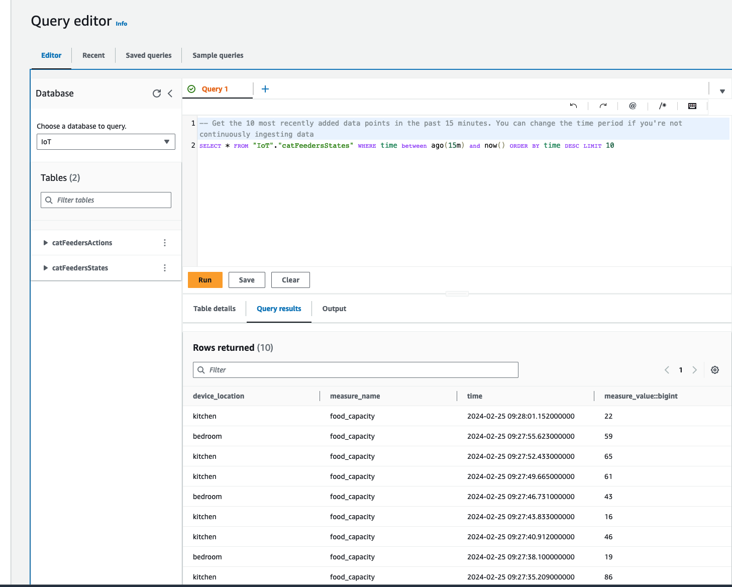
Query the data stored in the Amazon Timestream Database/Table
Now lets jump into the AWS Console, then jump into the Timestream Service and go into the "catFeedersStates" Table; then click on "Actions" to show the "Query table" option to go to the Query editor.
The Query editor will show a default query statement, click "Run" and you will see in the Query results the data from the MQTT messages that was generated by the script; where the MQTT messages was ingested from the IoT Topic "cat-feeder/states".
Recently I switched my Cat Feeder project's IaC to AWS CDK in favour of increasing my focus and productivity on building and iterating, rather than constantly mucking around with infrastructure everytime I resume my project after a break; which is rare and far between these days.
Just as with coding IoT microcontrollers such as the ESP32s, I want to get straight back into building every opportunity I get; so I am also switching away from Arduino based microcontroller development written in C++ - I don't have a background in C++ and to be honest this is the aspect I struggled with the most because I tend to forget things after not touching it for 6 months or so.
So I am switching to MicroPython to develop the logic for all my IoT devices going forward, this means I get to use Python - a programming lanaguge I work with frequently so there is less chance of me being forgetful when I use it at least once a month. MicroPython is a lean and efficient implementation of the Python 3 programming language that includes a subset of the Python standard library and is optimized to run on microcontrollers and in constrained environments - a good fit for IoT devices such as the ESP32!
What about all the Arduino hardware and components I already invested in?
Good news is MircoPython is supported on all ESP32 devices - based on the ones I myself have purchased; all I need to do to each ESP32 device is to flash it with a firmware - if you are impatient, you can scroll down and skip to below to the flashing the firmware section. When I first started Arduino, MicroPython was available to use, but that was 2 years ago and there were not as many good blog and tutorial content out there as there is today; I couldn't at the time work out how to control components such as sensors, servos and motors as well as I could with C++ based coding using Arduino; nowdays there are way more content to learn off and I've learnt (by PoCing individual components) enough to switch to MicroPython. As far as I understand it, any components you have for Arduino can be used in MicroPython, provided that there is a library out there that supports it, if there isn't then you can always write your own!
What's covered in this blog?
By the end of this blog, you will be able to send and receive MQTT messages from AWS IoT core using MicroPython, I will also cover the steps involved in flashing a MicroPython firmware image onto an ESP32C3. Although this blog has a focus and example on using an ESP32, this example can be applied to any micro-controllers of any brand or flavours, provided the micro-controller you are using supports MicroPython.
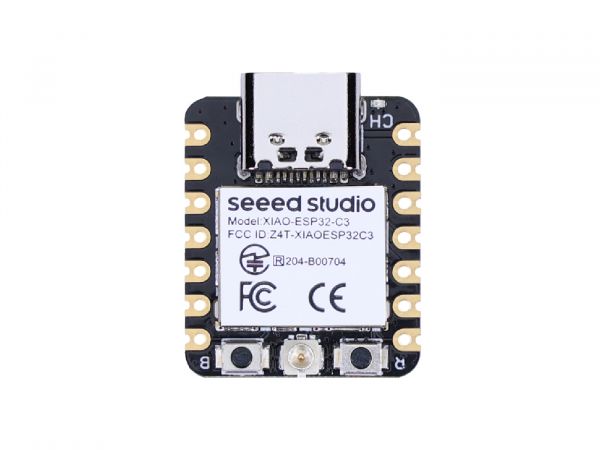
Flashing the MicroPython firmware onto a Seeed Studio XIAO ESP32C3
The following instructions works for any generic ESP32C3 devices!
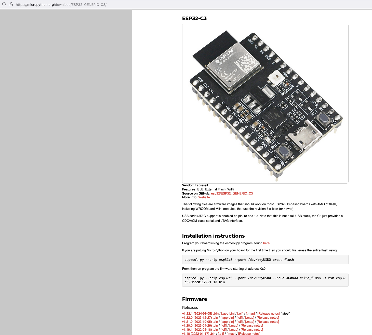
Download the latest firmware from micropython.org
Next, I connected my ESP32C3 to my Mac and ran the following command to find the name of the device port
/dev/ttyUSB0
My ESP32C3 is named "/dev/tty.usbmodem142401", the name for your ESP32C3 may be different.
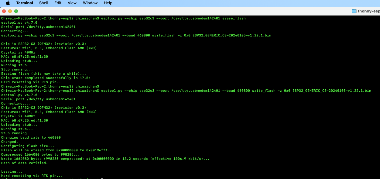
Next, install esptool onto your computer, then run the following commands to flash the MicroPython firmware onto the ESP32C3 using the bin file you've just downloaded.
It should look something like this when you run the commands.
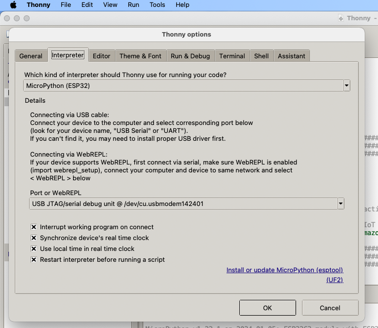
Install Thonny and run it. Then go to Tools -> Options, to configure the ESP32C3 device in Thonny to match the settings shown in the screenshot below.
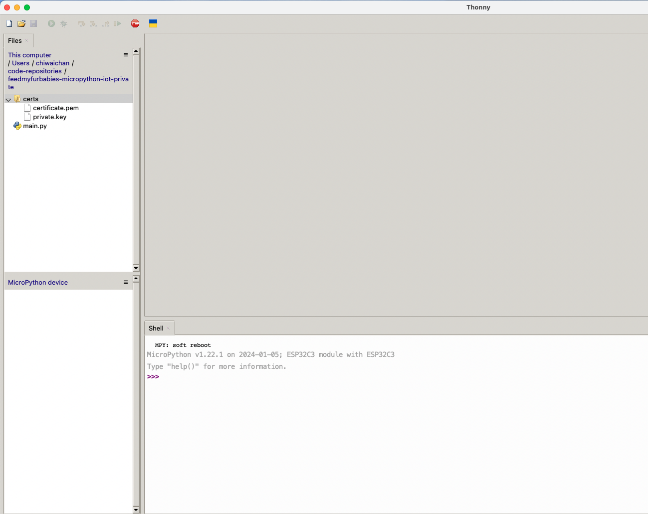
If everything went well, you should see these 2 sections in Thonny: "MicroPython Device" and "Shell", if not then try clicking on the Stop button in the top menu.
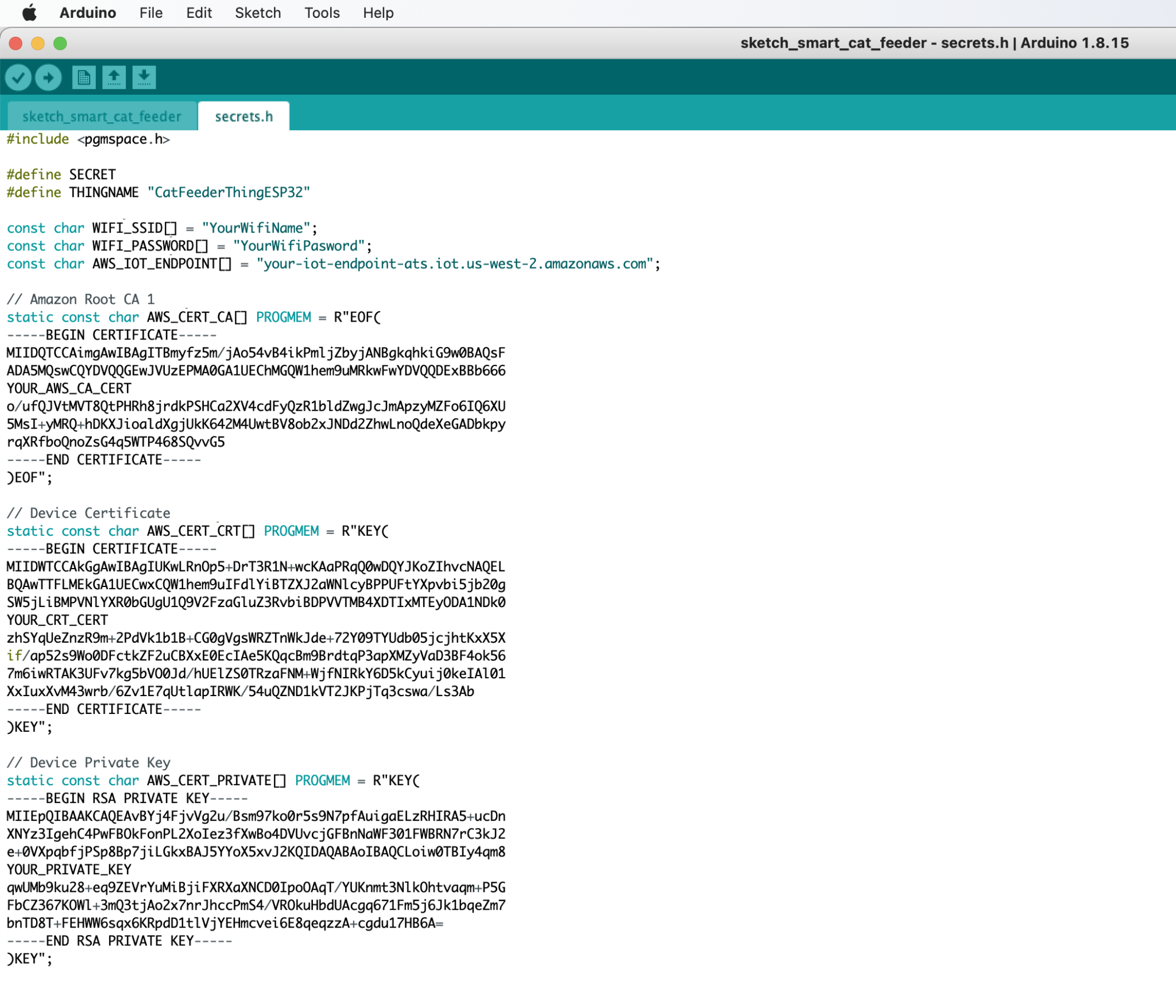
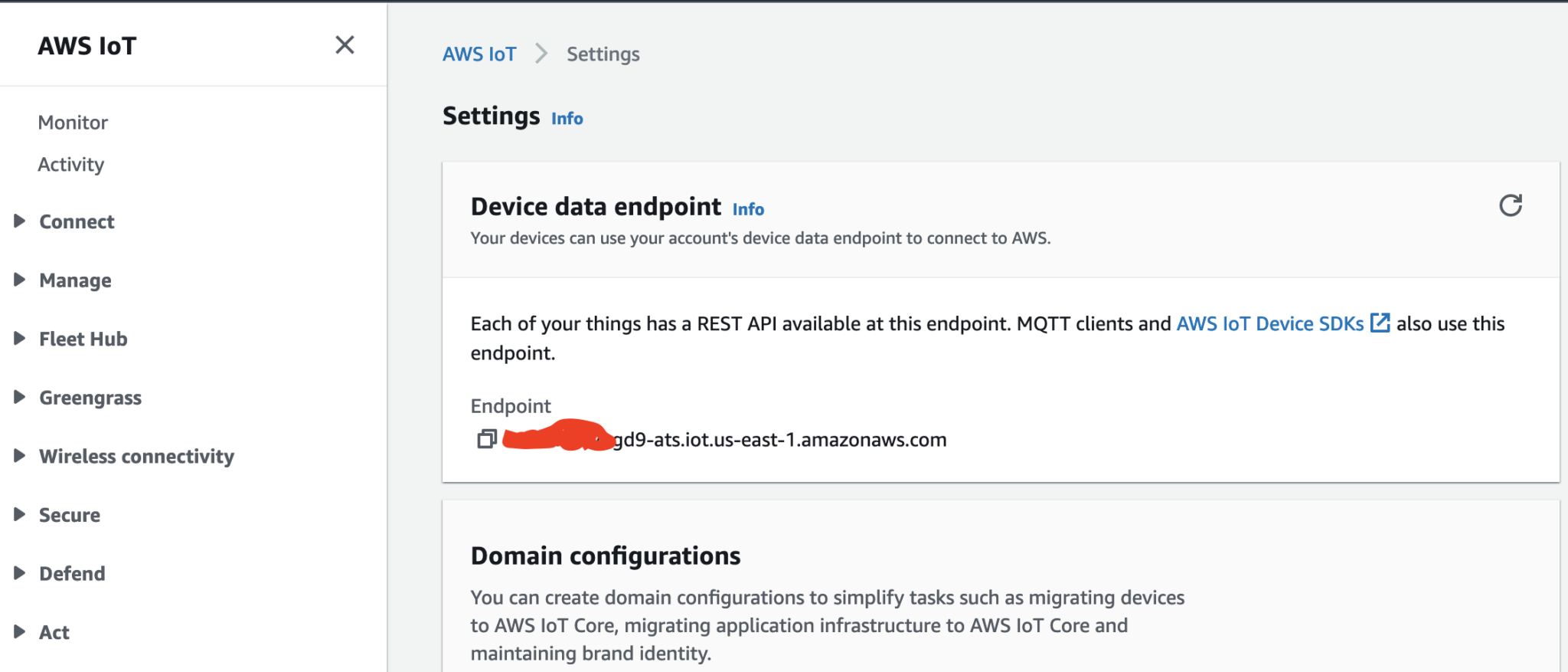
In order to send MQTT messages to an AWS IoT Core Topic, or to receive a message from a Topic in reverse, you will need a set of Certificate and Key\s for your micro-controller; as well as the AWS IoT Endpoint specific to your AWS Account and Region.
It's great if you have those with you so you can skip to the next section, if not, do not worry I've got you covered. In a past blog I have a reference architecture accompanied by a GitHub repository on how to deploy resources for an AWS IoT Core solution using AWS CDK, follow that blog to the end and you will have a set of Certificate and Key to use for this MicroPython example; the CDK Stack will deploy all the neccessary resources and policies in AWS IoT Core to enable you to both send and receive MQTT messages to two separate IoT Topics.
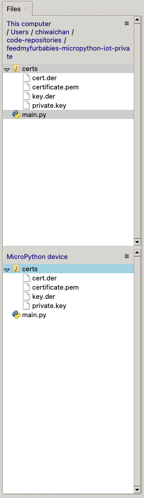
Now lets upload the MicroPython code to your micro-controller and prepare the IoT Certificate and Key so we can use it to authenticate the micro-controller to enable it to send and receive MQTT messages between your micro-controller and IoT Core.
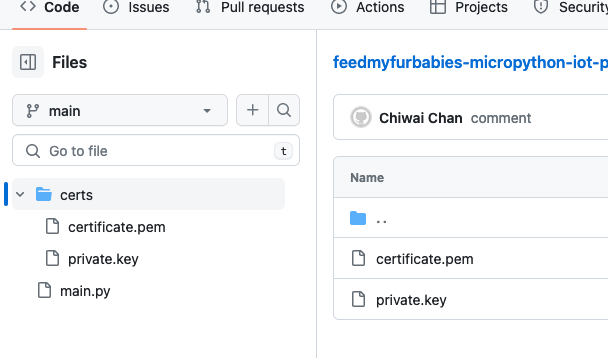
Copy your Certificate and Key into the respective files shown in the above screenshot; otherwise, if you are using the Certificate and Key from my reference architecture, then you should use the 2 Systems Manager Parameter Store values create by the CDK Stack.
Next we convert the Certificate and Key to DER format - converting the files to DER format turns it into a binary format and makes the files more compact, especially neccessary when we run use it on small devices like the ESP32s.
In a terminal go to the certs directory and run the following commands to convert the certificate.pem and private.key files into DER format.
openssl rsa -in private.key -out key.der -outform DER
openssl x509 -in certificate.pem -out cert.der -outform DER
You should see two new files with the DER extension appear in the directory if all goes well; if not, you probably need to install openssl.
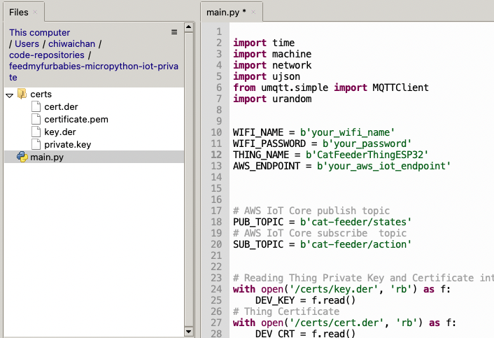
In Thonny, in the Files explorer, navigate to the GitHub repository's Root directory and open the main.py file. Fill in the values for the variables shown in the screenshot below to match your environment, if you are using my AWS CDK IoT referenece architecture then you are only required to fill in the WIFI details and the AWS IoT Endpoint specific to your AWS Account and Region.
Select both the certs folder and main.py in the Files explorer, then right click and select "Upload to /" to upload the code to your micro-controller; the files will appear in the "MicroPython Device" file explorer.
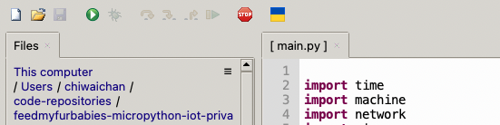
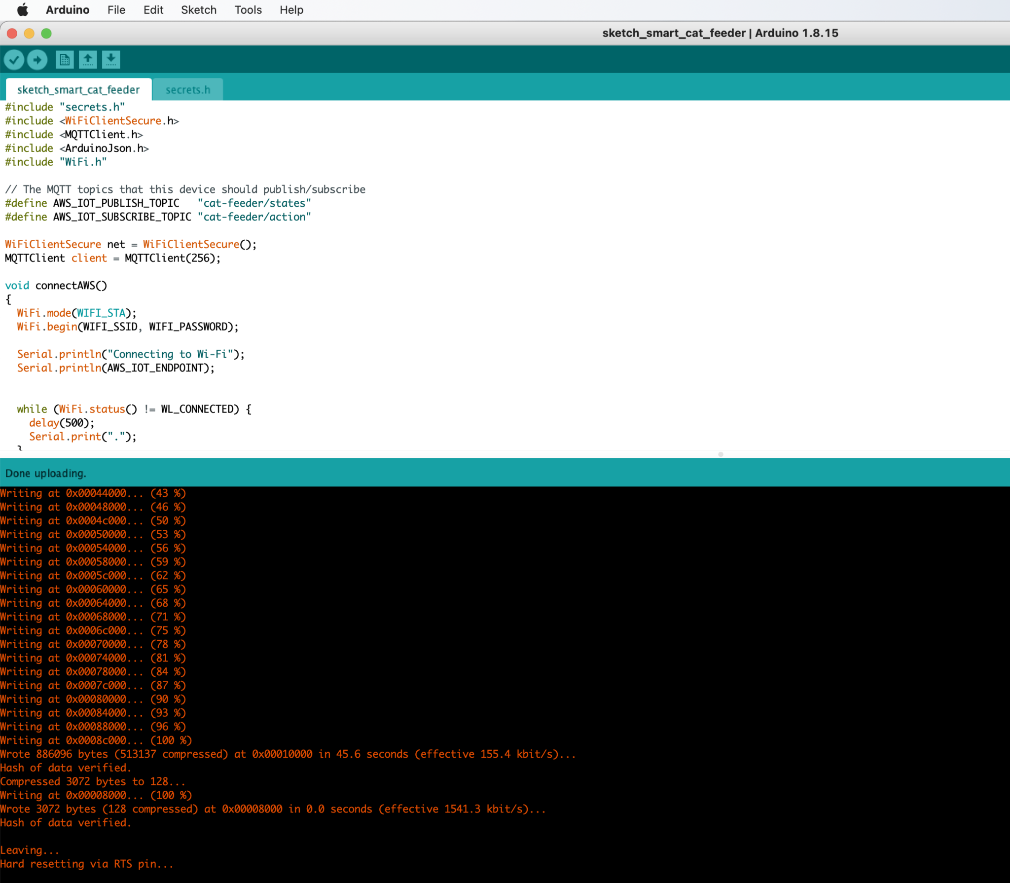
This is the moment we've been waiting for, lets run the main.py Python script by clicking on the Play Icon in green.
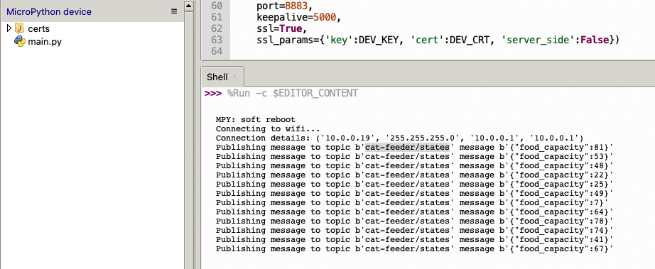
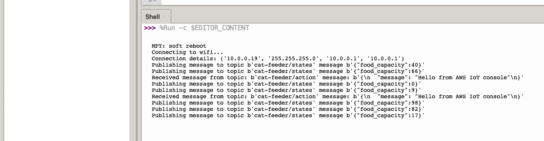
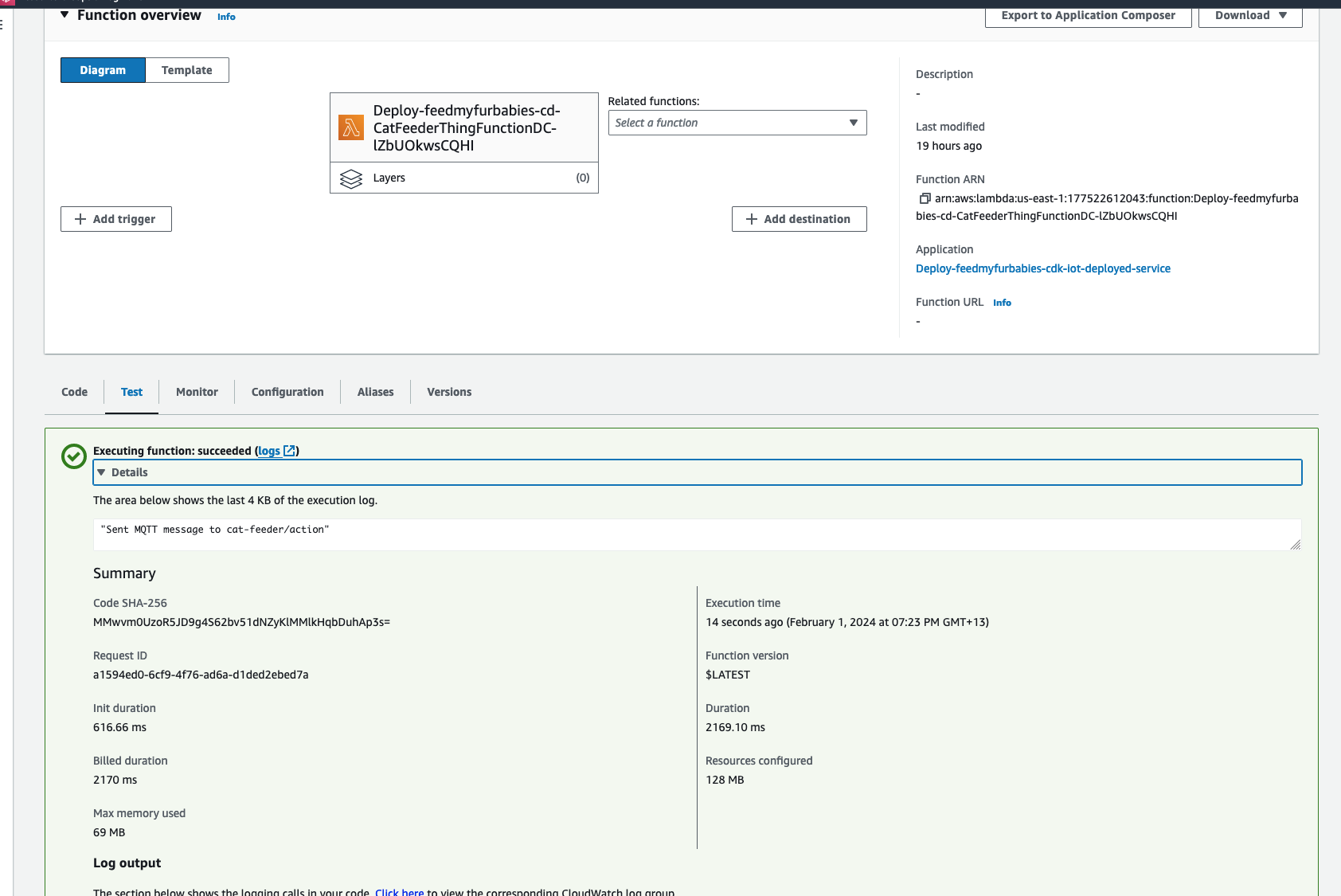
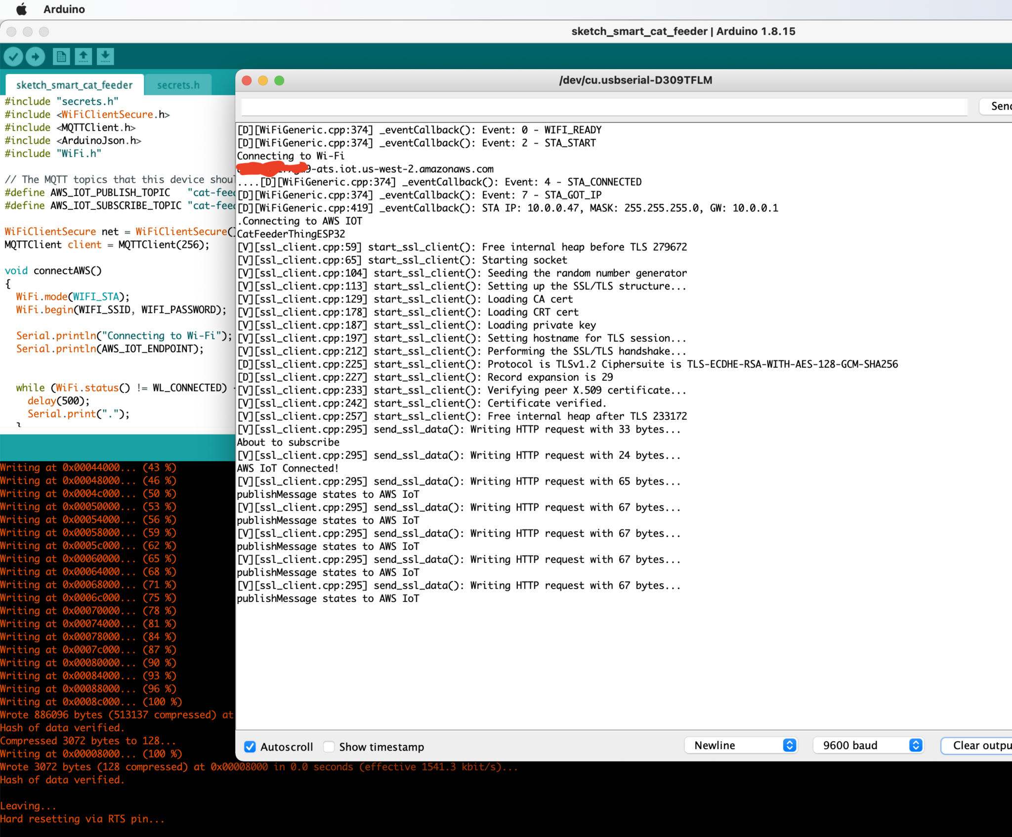
If all goes well you should see some output in the Shell section of Thonny.
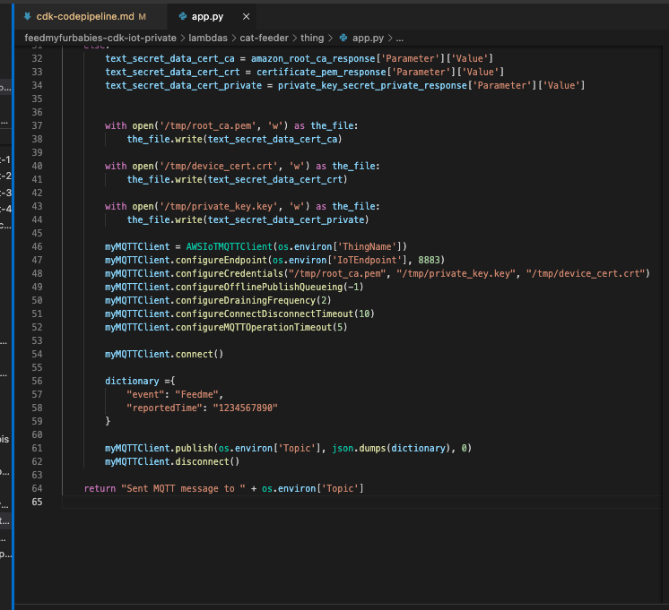
The code in the main.py file has a piece of code that is generating a random number for the food_capacity percentage property in the MQTT message; you can customise the message to fit your use case.
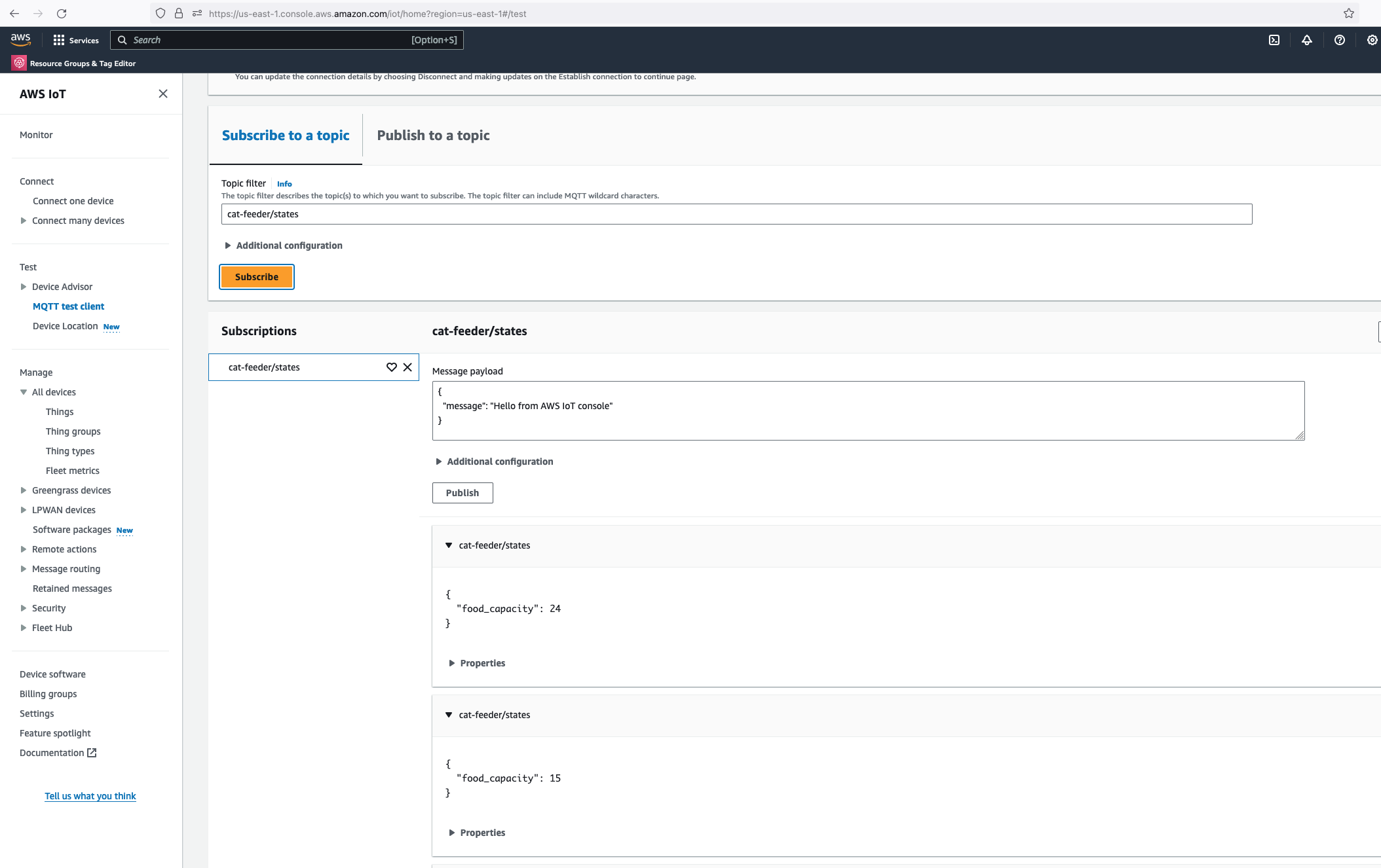
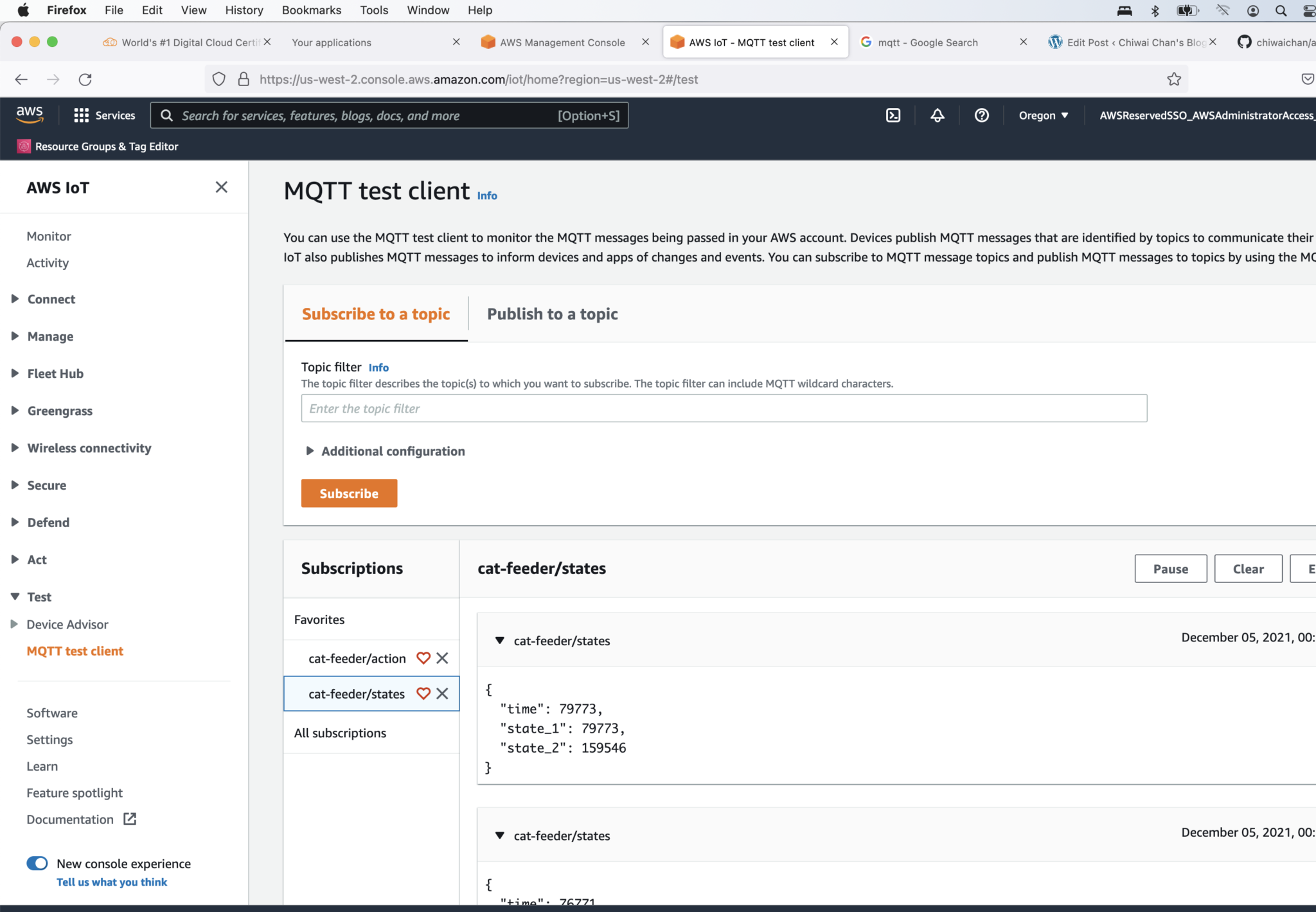
But lets verify it is actually received by AWS IoT Core.
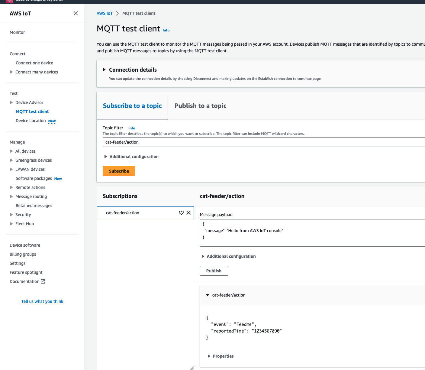
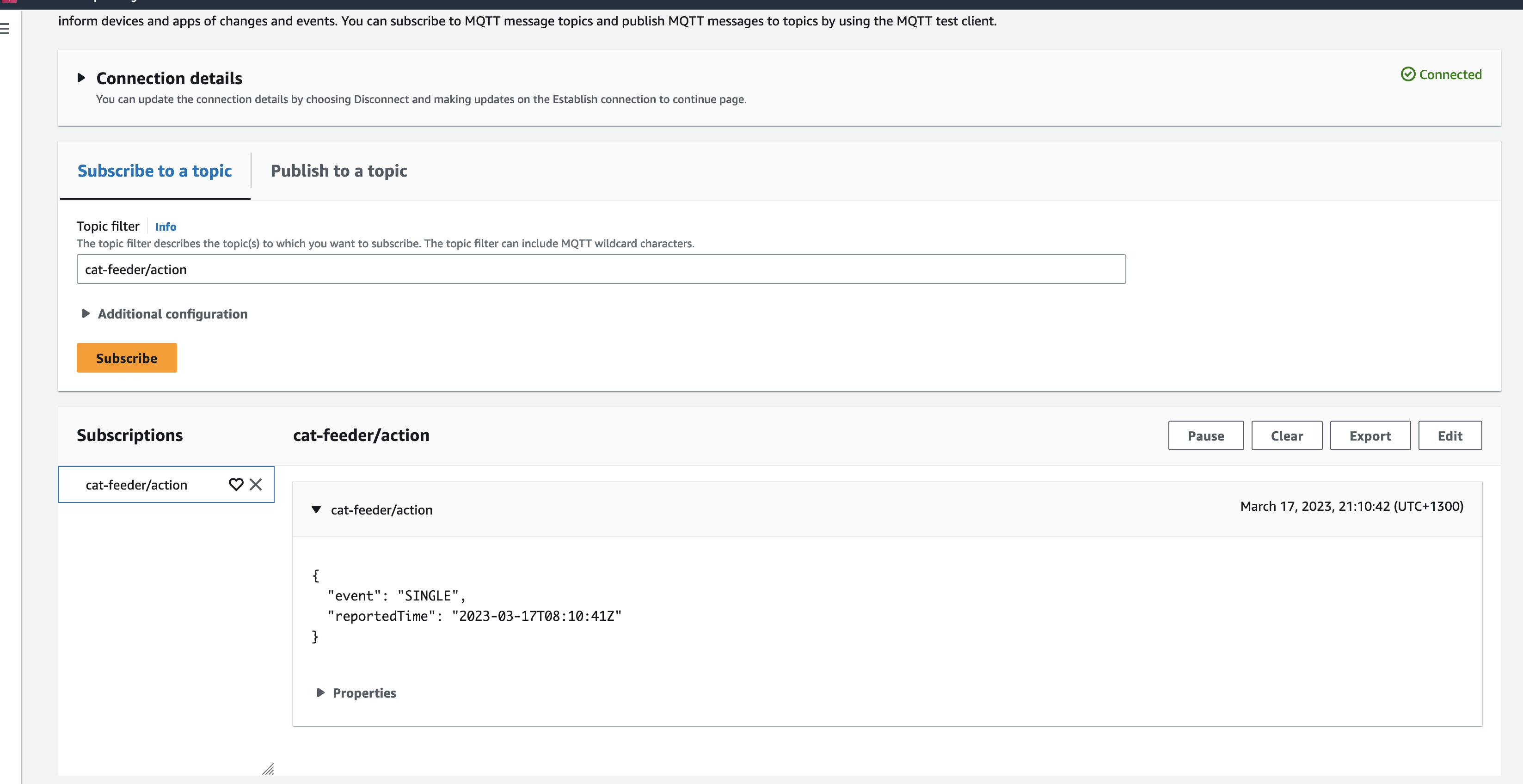
Alright, lets go the other way and see if we can receive MQTT messages from AWS IoT Core using the other Topic called "cat-feeder/action" we subscribed to in the MicroPython code.
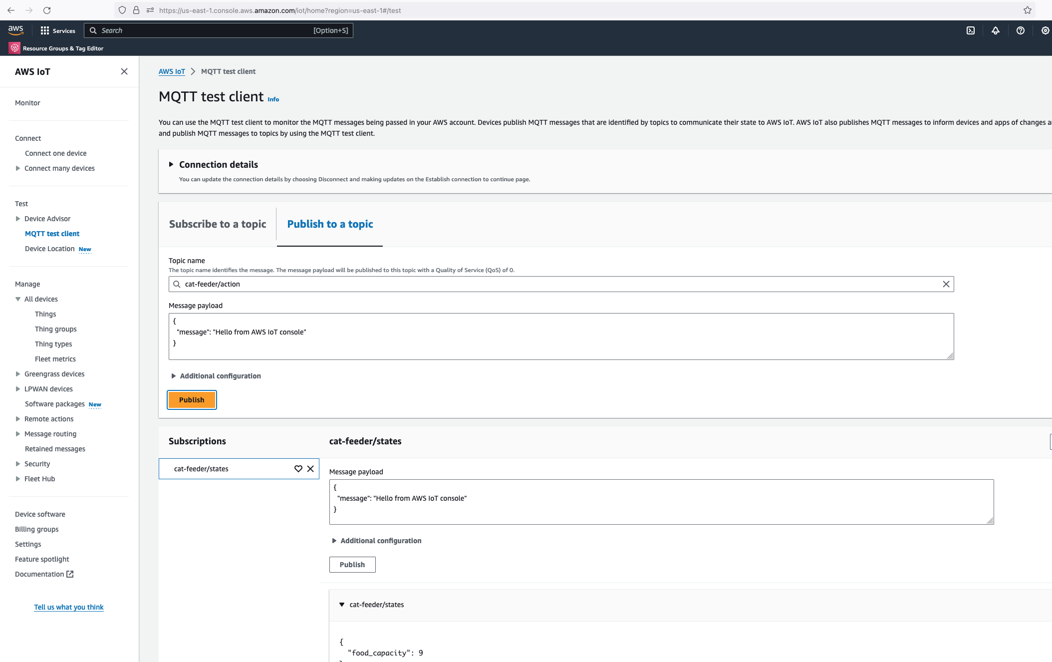
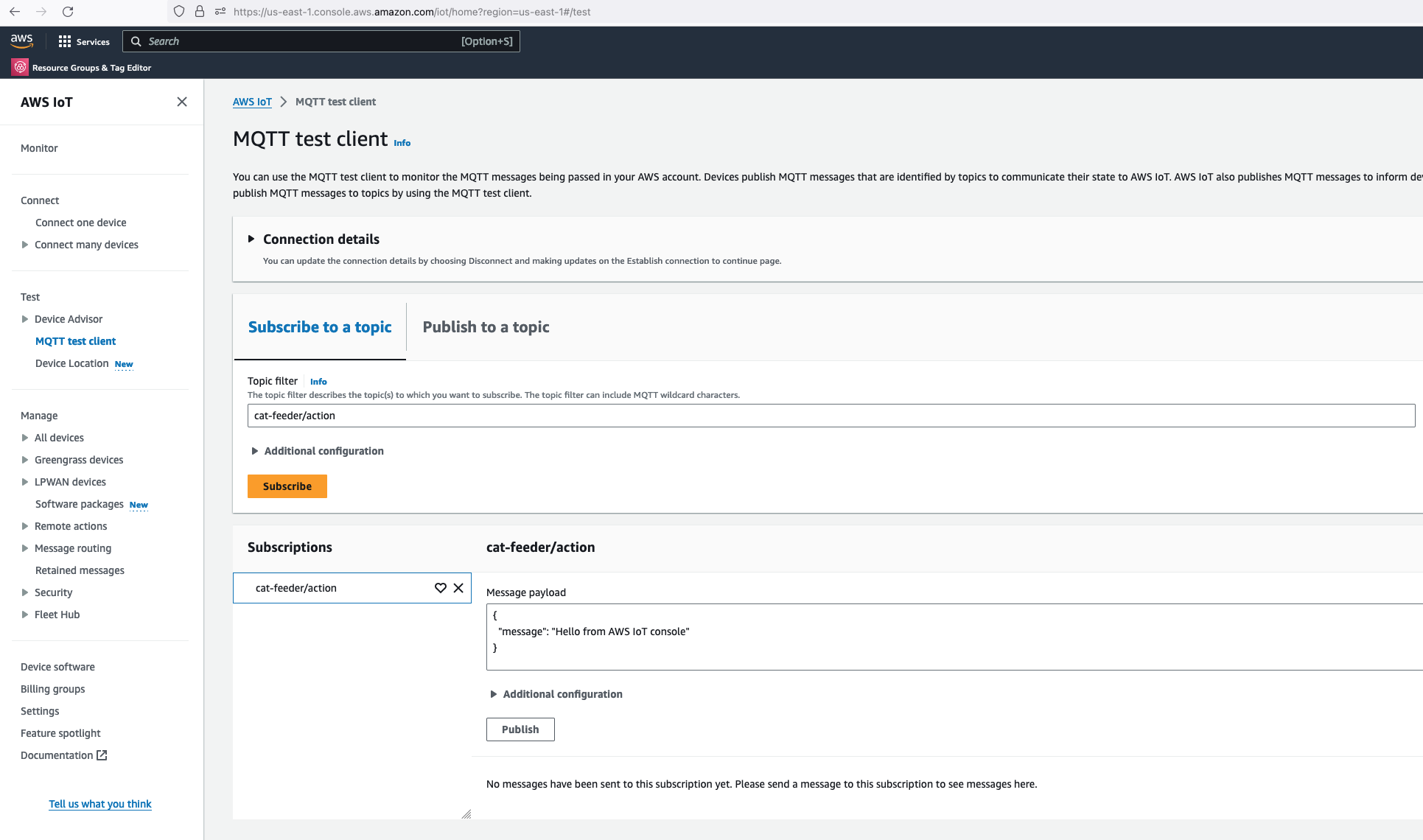
Lets go back the AWS Console and use the MQTT test client to publish a message.
In the Thonny Shell we can see the message "Hello from AWS IoT console" sent from the AWS IoT Core side and it being received by the micro-controller.
In a previous blog I talked about switching from CloudFormation template to AWS CDK as my preference for infrastructure as code, for provisioning my AWS Core IoT resources; I mentioned at the time whilst using resources using AWS CDK, as it would improve my productivity to focus on iterating and building.
Although I switched to CDK for the reasons I described in my previous blog, there are some CloudFormation limitations that cannot be addressed just by switching to CDK alone.
In this blog I will talk about CloudFormation Custom Resources:
What are CloudFormation Custom Resources?
What is the problem I am trying to solve?
How will I solve it?
How am I using Custom Resources with AWS CDK?
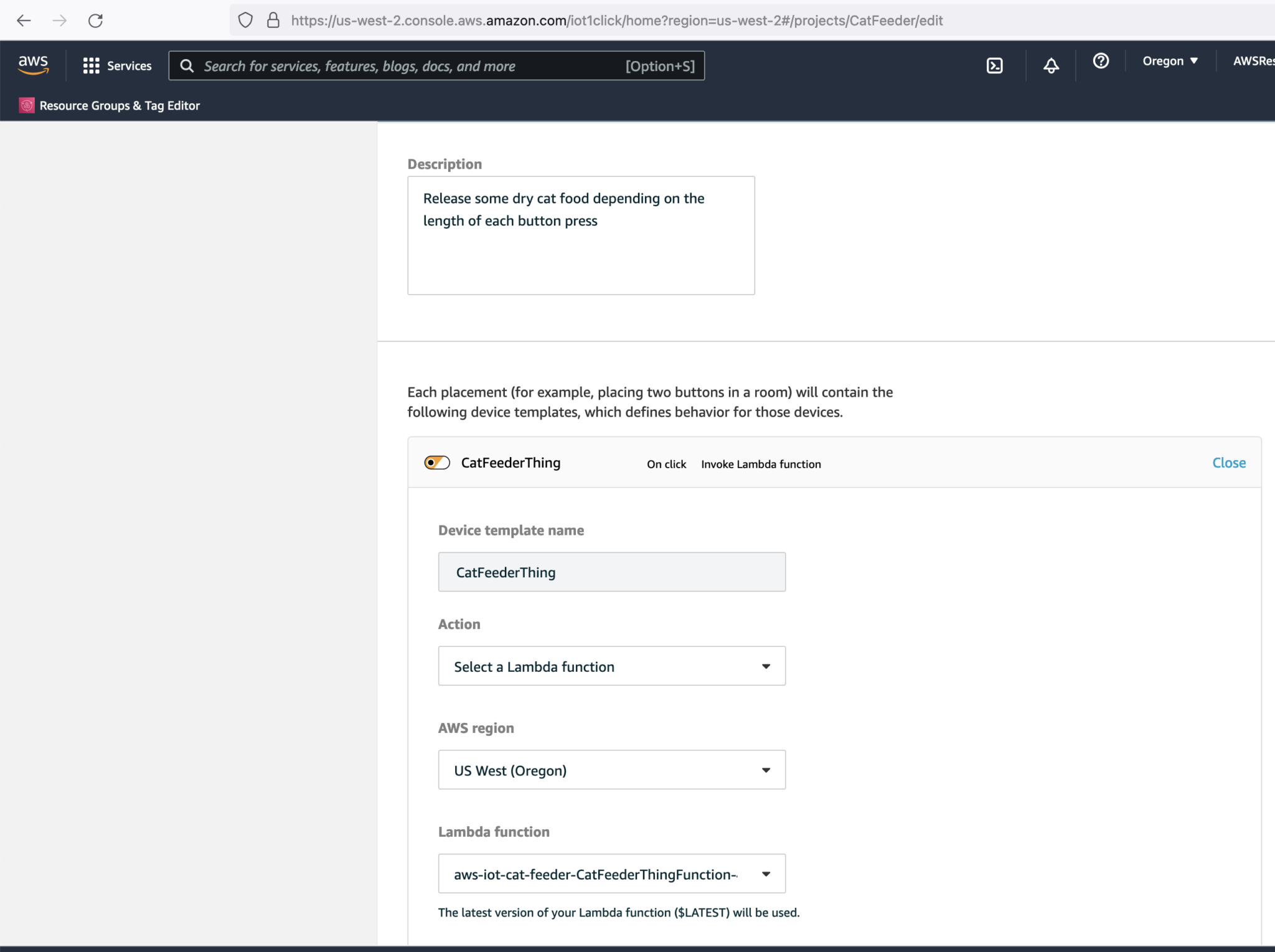
CloudFormation Custom Resources allows you to write custom logic using AWS Lambda functions to provision resources, whether these resources live in AWS (you might ask why not just use CloudFormation or CDK: keep reading), on-premise or in other public clouds. These Custom Resource Lambda functions configured within a CloudFormation template, and are hooked into a CloudFormation Stack's lifecycle during the create, update and delete phases - to allow these lifecycle stages to happen, the logic must be implemented into the Lambda function's code.
What is the problem I am trying to solve?
In my AWS IoT Core reference architecture, it relies on use of two sets of certificates and private keys; they are used to authenticate each Thing devices connecting to AWS IoT Core - this ensures that only trusted devices can establish a connection.
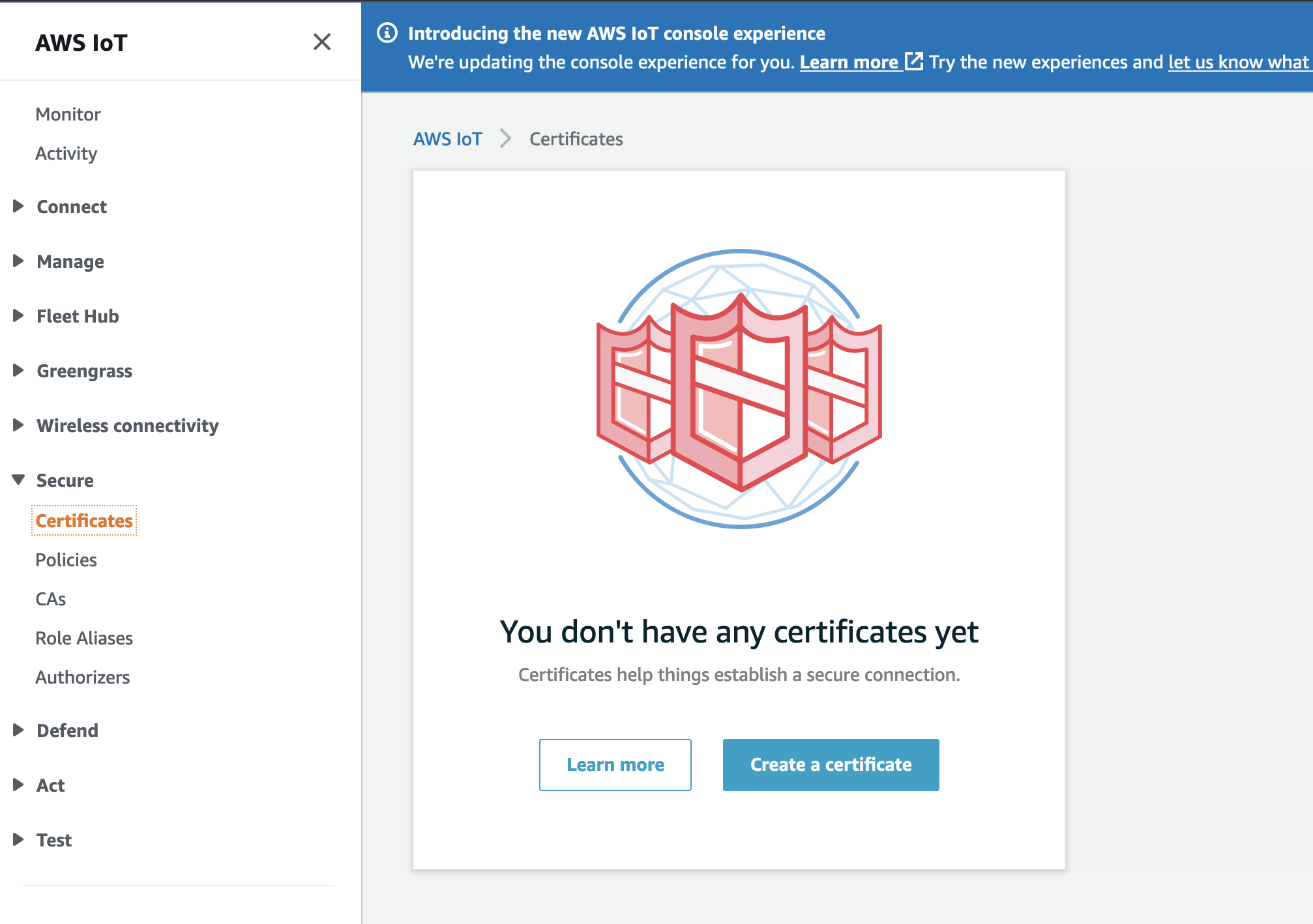
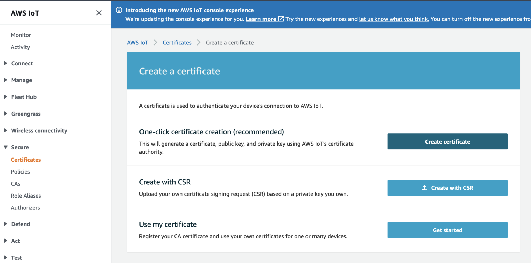
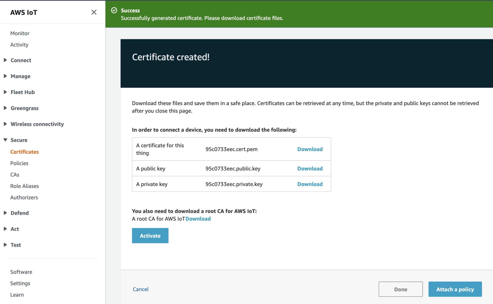
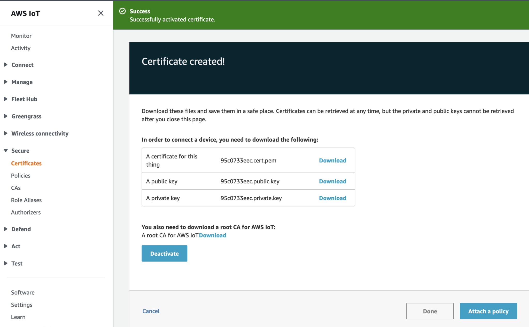
In the CloudFormation template version of my reference architecture, I had in the deployement instructions to manually create 2 Cetificates in the AWS Console for the IoT Core service, this is because CloudFormation doesn't directly support creation of certificates for AWS IoT Core; as shown in the screenshot below.
There is nothing wrong with creating the certificates manually within the AWS Console when you are trying out my example for the purpose of learning, but it would best to be able to deploy an entire set of resources using infrastructure as code, so we can achieve consistent repeatable deployments with as minimal effort as possible. If you are someone completely new to AWS, coding and IoT, my deployment instructions would be very overwheling and the chances of you successfully deploying a fully functional example will be very unlikely.
How will I solve it?
If you got this far and actually read what was written up to this point, you probably would have guess the solution is Custom Resources: so lets talk about how the problem described above was solved.
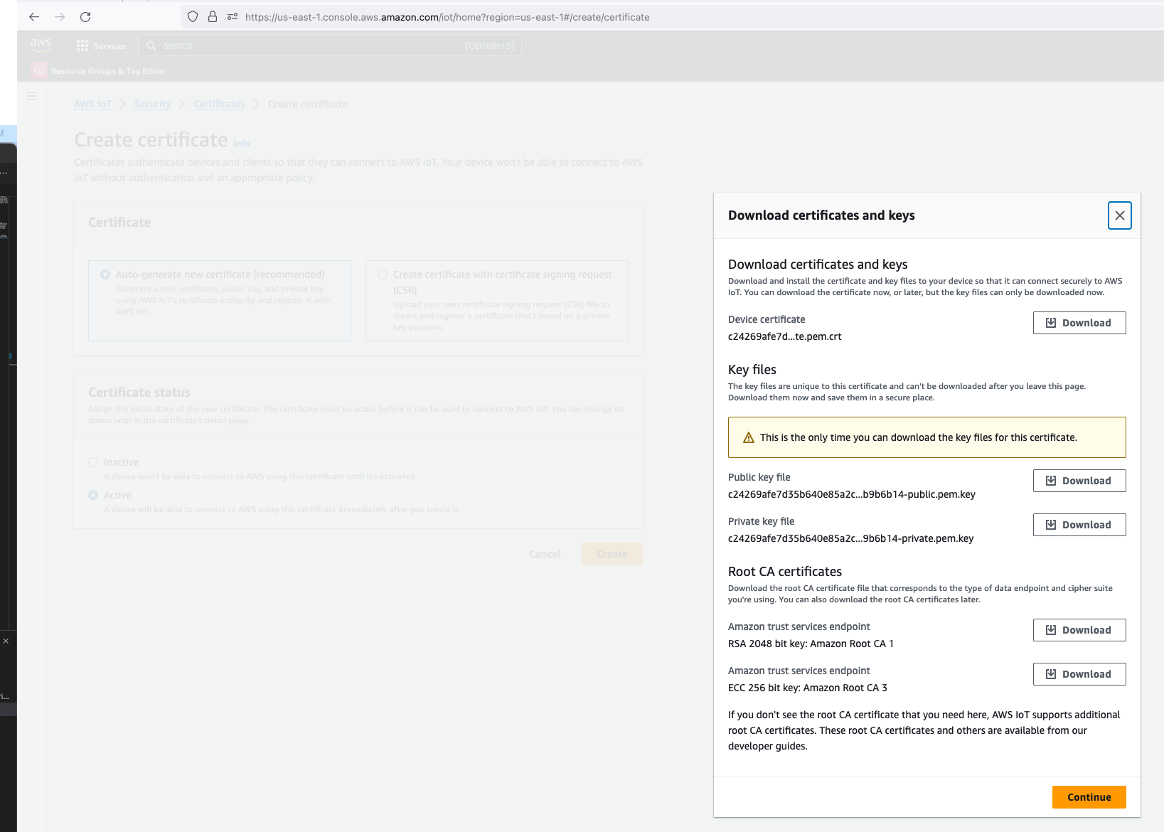
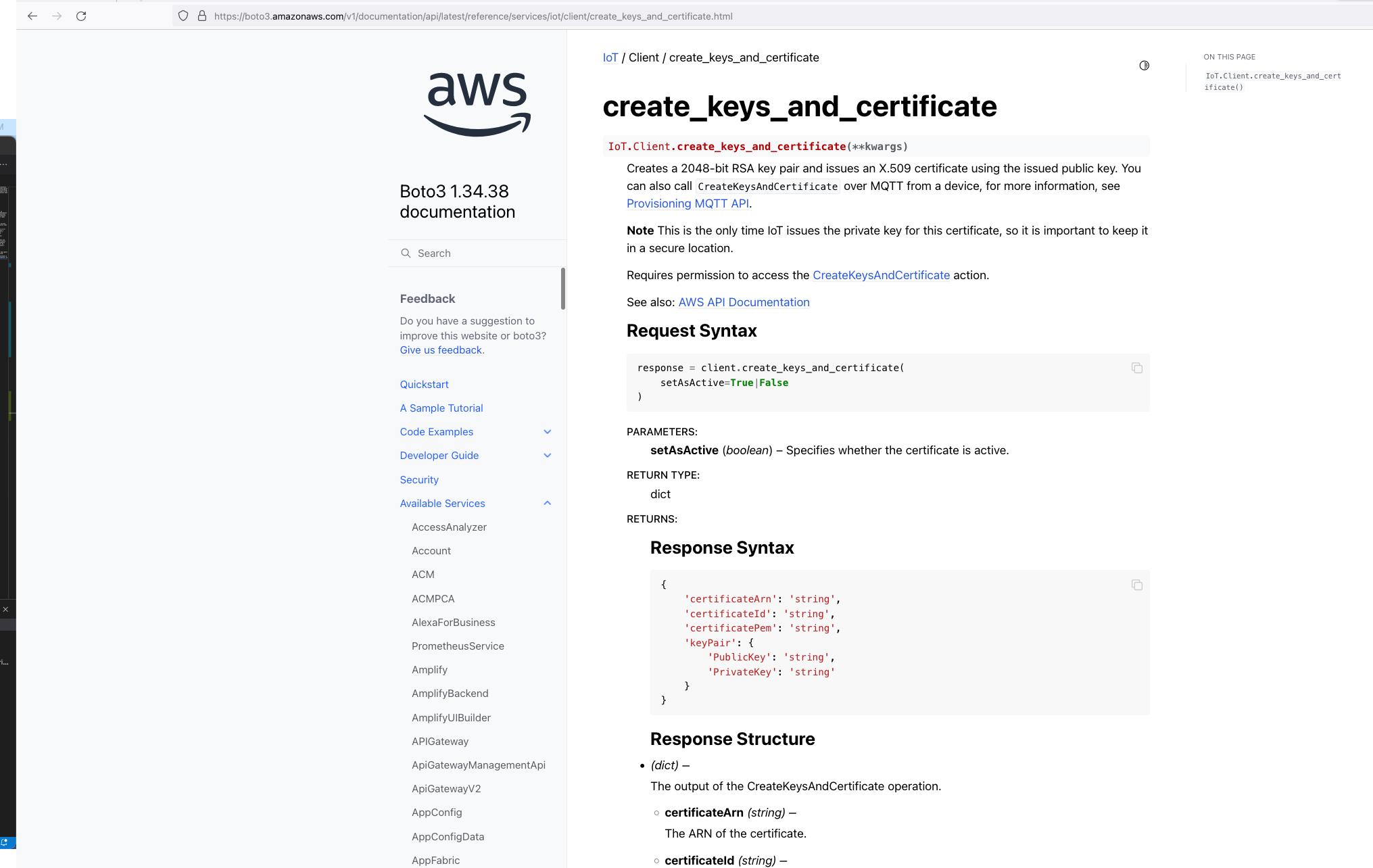
So we know Custom Resources is part of the solution, but one important thing we need to understand is that, even though there isn't the ability to create the certificates directly using CloudFormation, but there is support for creating the certificates using the AWS SDK Boto3 Python library: create_keys_and_certificate.
So essentially, we are able create the AWS IoT Core certificates using CloudFormation (in an indirectly way) but it requires the help of Custom Reources (a Lambda function) and the AWS Boto3 Python SDK.
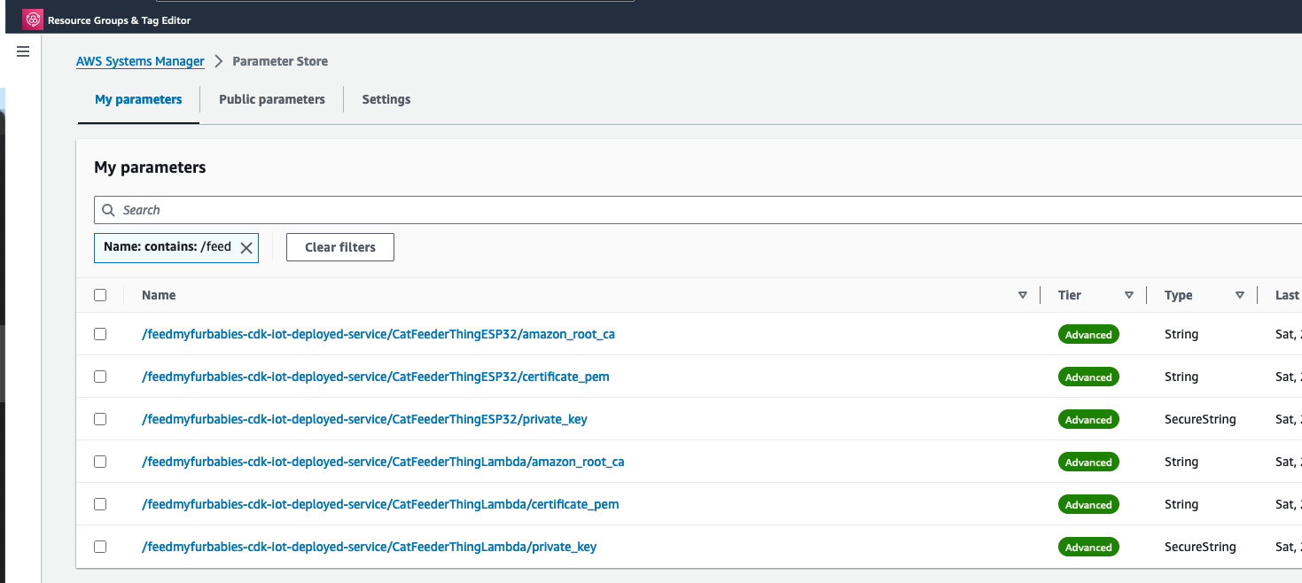
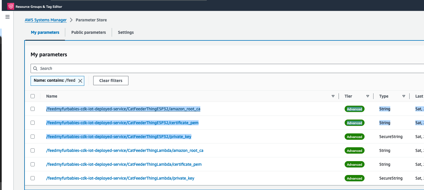
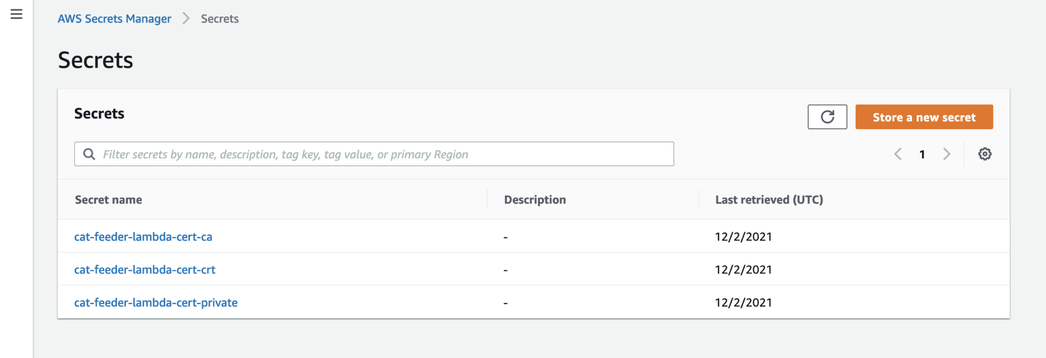
The Python code below is what I have in the Custom Resource Lambada function, it demonstrates the use of the Boto3 SDK to create the AWS IoT Core Certificates; and as a bonus, I am leveraging the Lambda function to save the Certificates into the AWS Systems Manager Parameter Store, this makes it much more simplier by centralising the Certificates in a single location without the engineer deploying this reference architecture having to manually copying/pasting/managing the Certificates - as I have forced readers in my original version of this reference architecture deployment.
The code below also manages the lifecycle of the Certificates as the CloudFormation Stacks are deleted, by deleting the Certificates it created during the create phase of the lifecycle.
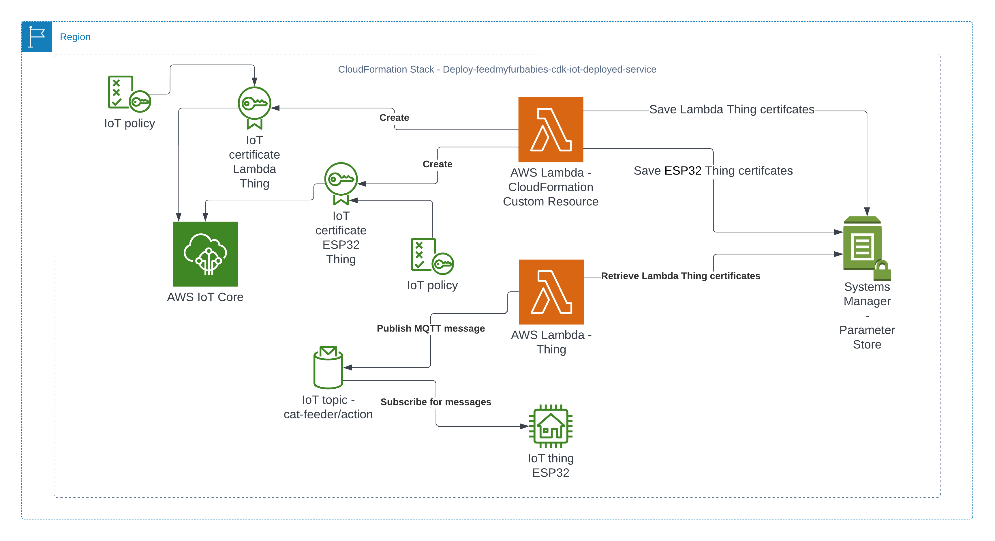
The overall flow to create the certificates is: Create a CloudFormation Stack --> Invoke the Custom Resource --> invoke the Boto3 IoT "create_keys_and_certificate" API --> save the certificates in Systems Manager Parameter Store
import os
import sys
import json
import logging as logger
import requests
import boto3
from botocore.config import Config
from botocore.exceptions import ClientError

import time

logger.getLogger().setLevel(logger.INFO)


def get_aws_client(name):
    return boto3.client(
        name,
        config=Config(retries={"max_attempts": 10, "mode": "standard"}),
    )


def create_resources(thing_name: str, stack_name: str, encryption_algo: str):

    c_iot = get_aws_client("iot")
    c_ssm = get_aws_client("ssm")

    result = {}

    # Download the Amazon Root CA file and save it to Systems Manager Parameter Store
    url = "https://www.amazontrust.com/repository/AmazonRootCA1.pem"
    response = requests.get(url)

    if response.status_code == 200:
        amazon_root_ca = response.text
    else:
        f"Failed to download Amazon Root CA file. Status code: {response.status_code}"


    try:
        # Create the keys and certificate for a thing and save them each as Systems Manager Parameter Store value later
        response = c_iot.create_keys_and_certificate(setAsActive=True)
        certificate_pem = response["certificatePem"]
        private_key = response["keyPair"]["PrivateKey"]
        result["CertificateArn"] = response["certificateArn"]
    except ClientError as e:
        logger.error(f"Error creating certificate, {e}")
        sys.exit(1)

    # store certificate and private key in SSM param store
    try:
        parameter_private_key = f"/{stack_name}/{thing_name}/private_key"
        parameter_certificate_pem = f"/{stack_name}/{thing_name}/certificate_pem"
        parameter_amazon_root_ca = f"/{stack_name}/{thing_name}/amazon_root_ca"

        # Saving the private key in Systems Manager Parameter Store
        response = c_ssm.put_parameter(
            Name=parameter_private_key,
            Description=f"Certificate private key for IoT thing {thing_name}",
            Value=private_key,
            Type="SecureString",
            Tier="Advanced",
            Overwrite=True
        )
        result["PrivateKeySecretParameter"] = parameter_private_key

        # Saving the certificate pem in Systems Manager Parameter Store
        response = c_ssm.put_parameter(
            Name=parameter_certificate_pem,
            Description=f"Certificate PEM for IoT thing {thing_name}",
            Value=certificate_pem,
            Type="String",
            Tier="Advanced",
            Overwrite=True
        )
        result["CertificatePemParameter"] = parameter_certificate_pem

        # Saving the Amazon Root CA in Systems Manager Parameter Store,
        # Although this file is publically available to download, it is intended to provide a complete set of files to try out this working example with as much ease as possible
        response = c_ssm.put_parameter(
            Name=parameter_amazon_root_ca,
            Description=f"Amazon Root CA for IoT thing {thing_name}",
            Value=amazon_root_ca,
            Type="String",
            Tier="Advanced",
            Overwrite=True
        )
        result["AmazonRootCAParameter"] = parameter_amazon_root_ca
    except ClientError as e:
        logger.error(f"Error creating secure string parameters, {e}")
        sys.exit(1)

    try:
        response = c_iot.describe_endpoint(endpointType="iot:Data-ATS")
        result["DataAtsEndpointAddress"] = response["endpointAddress"]
    except ClientError as e:
        logger.error(f"Could not obtain iot:Data-ATS endpoint, {e}")
        result["DataAtsEndpointAddress"] = "stack_error: see log files"

    return result

# Delete the resources created for a thing when the CloudFormation Stack is deleted
def delete_resources(thing_name: str, certificate_arn: str, stack_name: str):
    c_iot = get_aws_client("iot")
    c_ssm = get_aws_client("ssm")

    try:
        # Delete all the Systems Manager Parameter Store values created to store a thing's certificate files
        parameter_private_key = f"/{stack_name}/{thing_name}/private_key"
        parameter_certificate_pem = f"/{stack_name}/{thing_name}/certificate_pem"
        parameter_amazon_root_ca = f"/{stack_name}/{thing_name}/amazon_root_ca"
        c_ssm.delete_parameters(Names=[parameter_private_key, parameter_certificate_pem, parameter_amazon_root_ca])
    except ClientError as e:
        logger.error(f"Unable to delete parameter store values, {e}")

    try:
        # Clean up the certificate by firstly revoking it then followed by deleting it
        c_iot.update_certificate(certificateId=certificate_arn.split("/")[-1], newStatus="REVOKED")
        c_iot.delete_certificate(certificateId=certificate_arn.split("/")[-1])
    except ClientError as e:
        logger.error(f"Unable to delete certificate {certificate_arn}, {e}")


def handler(event, context):
    props = event["ResourceProperties"]
    physical_resource_id = ""


    try:
        # Check if this is a Create and we're failing Creates
        if event["RequestType"] == "Create" and event["ResourceProperties"].get(
            "FailCreate", False
        ):
            raise RuntimeError("Create failure requested, logging")
        elif event["RequestType"] == "Create":
            logger.info("Request CREATE")

            resp_lambda = create_resources(
                thing_name=props["CatFeederThingLambdaCertName"],
                stack_name=props["StackName"],
                encryption_algo=props["EncryptionAlgorithm"]
            )

            resp_controller = create_resources(
                thing_name=props["CatFeederThingControllerCertName"],
                stack_name=props["StackName"],
                encryption_algo=props["EncryptionAlgorithm"]
            )

            # The values in the response_data could be used in the CDK code, for example used as Outputs for the CloudFormation Stack deployed
            response_data = {
                "CertificateArnLambda": resp_lambda["CertificateArn"],
                "PrivateKeySecretParameterLambda": resp_lambda["PrivateKeySecretParameter"],
                "CertificatePemParameterLambda": resp_lambda["CertificatePemParameter"],
                "AmazonRootCAParameterLambda": resp_lambda["AmazonRootCAParameter"],
                "CertificateArnController": resp_controller["CertificateArn"],
                "PrivateKeySecretParameterController": resp_controller["PrivateKeySecretParameter"],
                "CertificatePemParameterController": resp_controller["CertificatePemParameter"],
                "AmazonRootCAParameterController": resp_controller["AmazonRootCAParameter"],
                "DataAtsEndpointAddress": resp_lambda[
                    "DataAtsEndpointAddress"
                ],
            }

            # Using the ARNs of the pairs of certificates created as the PhysicalResourceId used by Custom Resource
            physical_resource_id = response_data["CertificateArnLambda"] + "," + response_data["CertificateArnController"]
        elif event["RequestType"] == "Update":
            logger.info("Request UPDATE")
            response_data = {}
            physical_resource_id = event["PhysicalResourceId"]
        elif event["RequestType"] == "Delete":
            logger.info("Request DELETE")

            certificate_arns = event["PhysicalResourceId"]
            certificate_arns_array = certificate_arns.split(",")

            resp_lambda = delete_resources(
                thing_name=props["CatFeederThingLambdaCertName"],
                certificate_arn=certificate_arns_array[0],
                stack_name=props["StackName"],
            )

            resp_controller = delete_resources(
                thing_name=props["CatFeederThingControllerCertName"],
                certificate_arn=certificate_arns_array[1],
                stack_name=props["StackName"],
            )
            response_data = {}
            physical_resource_id = certificate_arns
        else:
            logger.info("Should not get here in normal cases - could be REPLACE")

        send_cfn_response(event, context, "SUCCESS", response_data, physical_resource_id)
    except Exception as e:
        logger.exception(e)
        sys.exit(1)


def send_cfn_response(event, context, response_status, response_data, physical_resource_id):
    response_body = json.dumps({
        "Status": response_status,
        "Reason": "See the details in CloudWatch Log Stream: " + context.log_stream_name,
        "PhysicalResourceId": physical_resource_id,
        "StackId": event['StackId'],
        "RequestId": event['RequestId'],
        "LogicalResourceId": event['LogicalResourceId'],
        "Data": response_data
    })

    headers = {
        'content-type': '',
        'content-length': str(len(response_body))
    }

    requests.put(event['ResponseURL'], data=response_body, headers=headers)
How I am using Custom Resources with AWS CDK?
What I am about to describe in this section can also be applied to a regular CloudFormation template, as a matter of fact, CDK will generate a CloudFormation template behind the scenes during the Synth phase of the CDK code in the latest version of my IoT Core reference architecture implemented using AWS CDK: https://chiwaichan.co.nz/blog/2024/02/02/feedmyfurbabies-i-am-switching-to-aws-cdk/
In my CDK code, I provision the Custom Resource lambda function and the associated IAM Roles and Polices using the Python code below. The line of code "code=lambda_.Code.from_asset("lambdas/custom-resources/iot")" loads the Custom Resource Lambda function code shown earlier.
# IAM Role for Lambda Function
        custom_resource_lambda_role = iam.Role(
            self, "CustomResourceExecutionRole",
            assumed_by=iam.ServicePrincipal("lambda.amazonaws.com")
        )

        # IAM Policies
        iot_policy = iam.PolicyStatement(
            actions=[
                "iot:CreateCertificateFromCsr",
                "iot:CreateKeysAndCertificate",
                "iot:DescribeEndpoint",
                "iot:AttachPolicy",
                "iot:DetachPolicy",
                "iot:UpdateCertificate",
                "iot:DeleteCertificate"
            ],
            resources=["*"]  # Modify this to restrict to specific secrets
        )

        # IAM Policies
        ssm_policy = iam.PolicyStatement(
            actions=[
                "ssm:PutParameter",
                "ssm:DeleteParameters"
            ],
            resources=[f"arn:aws:ssm:{self.region}:{self.account}:parameter/*"]  # Modify this to restrict to specific secrets
        )

        logging_policy = iam.PolicyStatement(
            actions=[
                "logs:CreateLogGroup",
                "logs:CreateLogStream",
                "logs:PutLogEvents"
            ],
            resources=["arn:aws:logs:*:*:*"]
        )

        custom_resource_lambda_role.add_to_policy(iot_policy)
        custom_resource_lambda_role.add_to_policy(ssm_policy)
        custom_resource_lambda_role.add_to_policy(logging_policy)

        # Define the Lambda function
        custom_lambda = lambda_.Function(
            self, 'CustomResourceLambdaIoT',
            runtime=lambda_.Runtime.PYTHON_3_8,
            handler="app.handler",
            code=lambda_.Code.from_asset("lambdas/custom-resources/iot"),
            timeout=Duration.seconds(60),
            role=custom_resource_lambda_role
        )


        # Properties to pass to the custom resource
        custom_resource_props = {
            "EncryptionAlgorithm": "ECC",
            "CatFeederThingLambdaCertName": f"{cat_feeder_thing_lambda_name.value_as_string}",
            "CatFeederThingControllerCertName": f"{cat_feeder_thing_controller_name.value_as_string}",
            "StackName": f"{construct_id}",
        }

        # Create the Custom Resource
        custom_resource = CustomResource(
            self, 'CustomResourceIoT',
            service_token=custom_lambda.function_arn,
            properties=custom_resource_props
        )
When you execute a "cdk deploy" using the CLI on the CDK reference architecture, CDK will synthesize from the Python CDK code, a CloudFormation template, and then create a CloudFormation Stack using the synthesized CloudFormation template for you.
I have been a bit slack on this Cat Feeder IoT project for the last 12 months or so; there have been many challenges I've faced during that time that prevented me from materialising the ideas I had - many of them sounded a little crazy if you've had a conversation with me in passing, but they are not crazy to me in my crazy mind as I know what I ramble about is technically doable.
Examples of the technical related challenges I had were:
CloudFormation: the initial version of this project was implemented using CloudFormation for the IaC, here is the repository containing both the code and deployment instructions. If you read the deployment instructions, you will notice there are a lot of manual steps required - e.g. creating 2 sets of certificates in AWS Iot Core in the AWS Console; and copying and pasting values to and from the CloudFormation Parameters and Outputs, even though at the time I made my best efforts to minimise the manual effort required while coding them. It was not a good example to get it up and running especially if you are new to AWS, Arduino or IoT; as I myself struggled at times to deploy my own example.
Terraform: I ported the CloudFormation IaC code to Terraform some time last year, you can find it here. Nothing is wrong with Terraform itself; I just keep forgetting to save or misplaced my terraform state files every time I resume this project. In reality I might leverage both Terraform and CDK for the projects/micro-services I create in the future, but it all really depends on what I am trying to achieve at the end of the day.
Deploying the AWS CDK version of this Cat Feeder IoT project
The commands above are all you need to execute in order to deploy the Cat Feeder project in CDK - assuming you have the AWS CDK and your AWS credentials configured on the machine you are calling these commands on; the first group of commands checks out the CDK code which deploys an AWS CodeCommit repository and a CodePipeline pipeline - creates the 1st CloudFormation Stack using a CloudFormation template; and the second group of commands pushes the CDK code into the newly created CodeCommit repository created in the first group of commands, which in turns trigger an execution in CodePipeline and the pipeline deploys the resources for this Cat Feeder IoT project - creates the 2nd CloudFormation Stack using a different CloudFormation template.
The two groups of commands creates the 2 CloudFormation Stacks shown in the screenshot below, the stack "feedmyfurbabies-cdk-iot" provisions the CodeCommit repository and CodePipeline - using the 1st CloudFormation template, and the stack "Deploy-feedmyfurbabies-cdk-iot-deployed-service" provisions the resources for this Cat Feeder IoT project - using the 2nd CloudFormation template.
FYI, I did not come up with the pattern I just described above that deployed the two CloudFormation Stacks: one for the pipeline and the other for the AWS resources for this Cat Feeder IoT project; I only came across it during one of those AWS online workshops I was using to learn CDK and noticed this pattern and found it useful, and pretty much decided to adopt it for my projects going forward.
Test out the deployed solution
The resources that are relevant to architecture of this AWS IoT solution are shown in the diagram below.
There are 2 sets of certificates and 2 sets of AWS IoT Things and policies deployed by the "Deploy-feedmyfurbabies-cdk-iot-deployed-service":
The 1st set of certificates and IoT Thing is hooked up to the AWS Lambda function (Lambda Thing) shown in the diagram, this Lambda function acts as an AWS IoT Thing (uses the certificates saved in Systems Manager Parameter prefixed with "/feedmyfurbabies-cdk-iot-deployed-service/CatFeederThingLambda") and is fully configured as one along with all the neccessary certificates and permissions to send an MQTT message to the "cat-feeder/action" topic in AWS IoT Core; this is a very convenient way to see in action how one could send MQTT messages to AWS IoT Core using Python, as well as a good way to confirm the deployment was successful by testing it out!
Before we invoke the Lambda Thing/function, we need to subscribe to the "cat-feeder/action" topic so that we could see the incoming messages sent by the Lambda function.
Then we invoke the Lambda function in the AWS Console:
Make sure you get a green box confirming the MQTT message was sent.
The code in the Lambda is written in Python and it sends a JSON payload (the dictionary variable shown in the code below) to the IoT Topic "cat-feeder/action"
Now lets go back to AWS IoT Core to confirm we have received the message:
We can see the message received in IoT Core is the dictionary object sent by the Lambda code
Conclusion
Using CDK does not eliminate all the issues you might encounter when using CloudFormation - I have a future blog on creating and using CloudFormation Custom Resources lined up; because at the end of the day CDK just generates a CloudFormation template and handles the deloyment of the CloudFormation Stack for you without you having to manage the CloudFormation Stacks or templates; the intent of this blog is to demonstrate how little effort is required to deploy an AWS IoT solution using CDK, compared with the same architecture I shared in my Github repo 2 years ago but with instructions using a CloudFormation template deployment that was long and tedious in manual steps.
The ultimate aim of change in IaC is to just focusing on building and iterating!
I do often talk too much in my blogs, but in this instance the instructions to deploy this solution for yourself to try out is very minimal, with the majority of the content focused on the resources deployed; and what each resource is for and how they interact with each other.
Extra
You may have noticed that there are 2 sets of certificates deployed in IoT Core and 2 IoT Things in this reference architecture, this is because you can take the 2nd set of certificates (prefixed with "/feedmyfurbabies-cdk-iot-deployed-service/CatFeederThingESP32") and Thing provisioned purely for you to send MQTT message to AWS IoT Core from your own IoT hardware devices / micro-controllers.
If you want to try it out, you will need to use the IoT Core Endpoint specific to your AWS Account and Region; you can either find it in the AWS IoT Core Console, or copy it from the CloudFormation Stack's Output:
The Lambda Thing we tested above can be used to send MQTT messages to your own IoT device/micro-controller, as the 2nd set of certificates is configured with the neccessary IoT Core Policies to receive the MQTT messages sent to the Topic "cat-feeder/action", and the certificates is also configured with the policies to send MQTT messages to a second IoT Topic called "cat-feeder/states"
I have a future blog that will demonstrate how to do this using MicroPython and a Seeed Studio XIAO ESP32C3 - so watch this space.
In my previous AWS IoT Cat feeder project I used a Lambda function as the event handler each time the Seeed Studio AWS IoT 1-click button was pressed, the Lambda function in turn published an MQTT message to AWS Iot Core which is received by the Cat Feeder (via a Seeed Studio XIAO ESP32C3 micro-controller) to dispense food into either one of the cat bowls or both (depending on the type of press performed on the IoT button). The long term goal is to integrate the AWS IoT Cat Feeder with the Feed My Fur Babies project.
In this Part 2 of the Feed My Fur Babies blog series, I will be introducing the Event-Sourcing pattern to the https://www.feedmyfurbabies.com architecture; describe the benefits of designing an architecture around Event-Souring and an example implemented using Terraform. I recently learnt Terraform and I now prefer it over the native IaC.
Here is the current state of the Cat Feeder architecture amd the IoT related resources previously deployed in AWS using CloudFormation:
The responsibilities of each of the resources deployed in the diagram prior to the introduction of the Event-Sourcing pattern into the architecture are:
AWS IoT 1-Click Button: This is an IoT button I physically press to emit an event to dispense food into one or both of the cat bowls, this button can be used anywhere where there is a WIFI connection
AWS IoT Core Certificates: Certificates are associated with resources and devices that interacts with the AWS IoT Core Service, either publishing an MQTT message to an AWS IoT Topic, or receiving an MQTT message from a Topic
AWS Lambda - IoT 1-Click Event Handler & sends an MQTT message to an Iot topic: This Lambda function is responsible for handling incoming events created by the AWS IoT 1-Click Button, as well as translating the event into an MQTT message before sending it to an AWS IoT Core Topic. This is the component in the architecture that is the main focus of this blog post, we will describe how this component will be re-architectured and decomposed to work in conjunction with the introduction of the Event-Sourcing pattern.
AWS IoT Core: This is the IoT service that manages the IoT Topics and Subcriptions to said Topics
Seeed Studio XIAO ESP32C3: a micro-controller subscribed to the IoT Topic (the one the Lambda sent MQTT messages to) that will dispense food into 1 or 2 cat bowls when it receives an MQTT message from the Topic
For further details on what role this architecture plays in the Smart IoT Cat Feeder, visit Part 2 of the Smart Cat Feeder Blog Series.
What is Event-Sourcing?
The idea of Event-Sourcing is to capture all events that occurs within a system during its lifetime, these events are stored in an immutable ledger in the sequence in which they occurred in.
One of the biggest benefits of capturing all the events of a system is that we are able to replay every single event that has ever occured within the system (partially or as a whole) at a later time (lets say 5 years later), and have the ability to selectively replay the 5 years worth of events to one or more specific downstream event bus targets: an event bus target could be a new application that was deployed into your production environment 5 years after the first event was created; what this means is that we could hydrate this new application's datastore with 5 years worth of data as if it existed at the beginning when the first event occured. Also, imagine being able to re-create entire datastores with the full history for 100s of applications (where each application has its own datastore) within your system landscape, these datastores could be hydrated with the full history of events stored in the immutable Event-Sourcing ledger, or even replay the events that occur from the very first event and up to a specific event at a given point in time (e.g. half of the entire ledge) - effectively providing you with the ability to create any datastore in any datastore engine with the data inside in a state to any given point in time.
How do we introduce Event-Sourcing into the architecture?
We start off with the AWS Lambda function shown in the current state architecture where its responsibilites is to handle the events received from the AWS IoT 1-Click Button each time it is pressed, as well as sending an MQTT message to an AWS Iot Core Topic in response to each incoming event; essentially it has 2 distinct responsibilities
Next, we decompose the single Lambda function into 2 separate distinct Lambda functions based on its 2 responsibilities, then we chain the 2 Lambda functions together to preserve its functionality - what we have effectively achieved by doing this is decoupling the 2 responsibilities as 2 separate units of work - resulting in 2 separate compute resources.
The benefits by a decoupled architecture are:
Each of the Lambda functions can be implemented in different languages - e.g. one in Python and the other can be in Java
Independent release cycles for each of the Lambda functions
Changes to either one of the 2 responsibilities can be made independently of each other
Each Lambda function can be scaled independently of another
In this step we use Amazon EventBridge as the Event-Sourcing store - known as the immutable ledger we described earlier, we will also leverage EventBridge as a serverless event bus to help us receive, filter, transform, route and deliver events to downstream services (event bus targets).
In this instance we will slip EventBridge in between the 2 Lambda functions and we will be storing every single IoT event sent by the IoT Button into the immutable ledge,
Benefits of adding EventBridge to the architecture:
The IoT 1-Click Lambda handler no longer directly calls the downstream Lambda function - so it is unaware of the downstream targets
The IoT events are stored in an immutable ledger in the sequence in which they occurred in
Prepare the system landscape with the ability to more easily develop micro-services in an Event-Driven architecture using the orchestration pattern
Target State Architecture
This is the end result of introducing Event-Sourcing to the architecture; it may not look like much benefits has been gained from adding Amazon EventBridge - in fact one might think that we've added more components and in effect created more moving parts and complexity. But I have decided to specifically introduce this very early into the architecture as an investment so that I am in a position to rapdily build out my micro-service architecture - reaping the rewards from the get go.
Try it out for yourself
I have created a GitHub Repository to deploy a complete working example of the resources shown in the Target State Architecture using Terraform.
I suggest you deploy this to have a play for yourself:
Clone the repository: "git clone git@github.com:chiwaichan/feedmyfurbabies-202303-eventsourcing-using-eventbridge.git"
Setup your Terraform environment
Run: "terraform init && terraform apply"
Also, check out each individual resource deployed by this Terrafrom code.
Create a test IoT 1-Click event to pass the event end-to-end through all the deployed resources
This is the IoT 1-Click Lambda function handler shown in the AWS Console
Create a test event so we can invoke the Lambda function to simulate an event as if a physical IoT Button is pressed
Here we can view the logs for this Lambda function Test invocation
The IoT 1-Click Lambda function handler sends an Event to the Custom EventBridge Event Bus named "feedmyfurbabies"
The event sent to the Custom Event Bus matches on the "source" attribute with a value of "com.feedmyfurbabies" with the Custom Event Bus Rule named "feeds-rule"
This Lambda function is the downstream target of the Custom Event Bus Rule that was mactched by the event and is responsible for interpreting the event message and translate it into an MQTT message, then in turn sends it to the AWS IoT Core Topic "cat-feeder/action" that you can subscribe to using a micro-controller, e.g. Seeed Studio XIAO ESP32C3.
Here we can see the logs of the event received by the EventBridge Custom Bus Rule
In the AWS Console for the AWS Iot Core Service, we can subscribe to Topics to receive an MQTT message right at the end of the downstream services - this is useful if you don't use a micro-controller
Future State Architecture
We end up with an architecture that will enable us to easily add targets to consume events managed by the EventBridge Custom Event Bus, doing so in a way where the IoT 1-Click Lambda function has no knowledge of any newly created subscribers of the Custom Event Bus.
Months prior to the very first lockdown I had gotten myself on the waitlist for a 4x4 Jimny, so I could take it to the beach without worrying about getting beached like I likely would in a regular front wheel drive hatchback; or take it to the bushes to climb some hills and see how far I would get without flipping it (badly). Knowing I wouldn't be able to drive it for an long indefinitely amount time so I decided to cancel the order back then; in some ways I was sad then but in many ways I am happy now that I have had a fair amount of time to have a good think about what else I could do with the Jimny whilst taking it on these adventures.
The time spent mulling has lead to another new blog series; this will take on a similar build approach I took while building my Iot Cat Feeder, but this time it will be on a larger scale in terms of the amount of moving parts and components; also, I would get to enjoy myself this time instead of the cats. For those that are unfamiliar with the approach I took in my prior build, I will start the blog series by proposing an idea I have in mind with a certainty of about 70% of achieving a functional prototype - this is mainly due to not having the background nor experience on most of the skills required to build out this idea.
Generally, I would create a new Part for the Blog Series as I achieve a milestone during the build, where I talk about what was achieved in the milestone and provide the details on how I got there; where possible I would include a public Github repository for any code written for the build.
As you may have already predicted what is involved in this build from the image above, yes it will involve a 4x4 - I have a Jimny on the way; and some cloud buzz words like Iot and Machine Learning.
The goals of this build is to:
Develop a solution to capture video recordings of my 4x4 adventures of the entire journey with 5+ viewpoints around the vehicle in 4K resolution, realistically I might only be about to capture full HD videos as explained further down this blog.
Capture and store the vehicle's telemetries at regular intervals as the vehicle is driven using the CAN Bus protocol, e.g. speed, RPM of the engine and any other states the car is in.
Capture other useful data not monitored by the vehicle's CAN Bus, such as GPS co-ordinates and the environment where the vehicle is at during the time - e.g. temperature, humidity, luminosity and many more using hand picked sensors.
Ingest in real time all the videos, CAN Bus and sensor data captured into an AWS Datalake
If I were able to achieve all the goals in the list above, then I would like to also achieve these goals:
Create a Digital Twin using AWS TwinMaker of the Jimny and associate all the sensors and devices captured with it
Train Machine Learning models using the data ingest in the AWS Datalake
Do something with the AWS Deeplens sitting in my draw for the past year with the ML models created above, perhaps warn me I am able to do something that will cause the Jimny to land on its roof like last time by making predictions on an ML model.
Have some sort of cloud solution that spits out a video for each of my trips so I can use it to upload to YouTube, with the video displaying some of the telemetries and sensor data captured.
At the end of the blog series I will conclude whether I was able build something that was functional, and whether or not I was able to achieve all the goals I have stated in the 2 lists above.
It has been a bit of a challenge to source certain types of electronic components at the moment as some may already know, so I've only managed to source the majority of components required at this point in time.
I had been wanting one of these for a long time so when I saw it on special I jumped on it straight away. This is the RV version so it means it can be taken anywhere with me, so I will mount this on a roof rack - one reason why I do not want to have the Jimny on its roof because it would not be fun to be somewhere with no internet for a long period of time.
The ideal location to place the Starlink is in a spot with no obstruction and as far away from everything as possible, however, when I tested it out in my tiny back yard with it sitting in the center surrounded by 2 houses (both 2 stories) and a high fence, I got the following results:
Although the speed is as fast as you get on the one of the slowest fibre plan available in New Zealand, the upload speed is the ultimate factor that determines how many live feeds we can ingest into the Datalake; a 4K resolution video is 20Mbps so that does not leave much bandwidth for all of the other data types, results may be better depending on where I am at the time, and also, unless Starlink offers symmetrical upload speeds then we are forced with full HD feeds, FYI download speeds can be as high as 500Mbps in some parts of the world. One option is to store the data onto a NAS drive via the Home Assistant installed on the LinkStar - a device similar to a Raspberry PI, then upload the videos into the Datalake after I get home - I like to avoid this as it is too much admin.
I also have some spare cameras to use; the feed on these can be served using the RTSP protocol, I also have a few ESP32-CAMs I recently purchased so this build will use a combination of the 2 camera types. Most webcams can be used for this.
I have a bunch of these as they are my go tos when I build projects using micro-controllers; they are like $5 USD: Seeed Studio XIAO ESP32C3, one of, if not the smallest ESP32s I've come across and is more reliable than other ones I've used previously.
I also have various sensors for use that measures:
I'm starting a new blog series where I will be documenting my build of a full-stack Web and Mobile application using AWS Amplify to implement both the frontend, as well as the backend; whilst developing dependent downstream Services outside of Amplify using AWS Serverless components to implement a Micro-Service architecture using Event-Driven design pattern - where we will break the application up into smaller consumable chunks that works together well.
Since we are creating from scratch a completely new application, I will also incorporate a vital pattern that will reduce complexity throughout the lifetime of the application: we will also be implementing the application using the Event-Sourcing pattern - this pattern ensures every Event ever published within a system is stored within an immutable ledger; this ledger will enable new Data Stores of any Data Store Engine to be created at any given time by replaying the Events in the ledger, of Events created from a start date and time to an end Date and Time.
CQRS is a pattern I will write up about with great detailed in a blog in the near future, CQRS will enable the ability to create mulitple Data Stores with identical data, each Data Store using a unique Data Store Engine instance.
Amplify is an AWS Service that provides any frontend web or mobile developers with no cloud expertise the ability to build and host full-stack applications on AWS. As a frontend developer, you can leverage it to build and integrate AWS Services and components into your frontend without having to deal with the underlying AWS Services; all Services the frontend is built on top of is managed by AWS Amplify - e.g. no need to managed CloudFormation Stacks, S3 Storage or AWS Cognito.
My experience from a while ago was full-stack application development and I have worked under that role for over 10 years, I've used various frontend/backend frameworks, components and patterns.
I will be building a website called Feed My Fur Babies where I will provide video streams showing live feeds of my cats from web cams placed in various spots around my house, the website will also provide users with the ability to feed my cats using internet enabled devices like the IoT Cat Feeders I recently put together and watch them hoon on their favorite treats; although I am experienced with building websites from the ground up using AWS Service, I am aiming to build Feed My Fur Babies whilst leveraging as little as possible on that experience - this is so I am building the website as close to the targeted demographics skillset of a typical Amplify as possible, i.e. as a developer with only frontend experience.
Current Architecture State
Update
Let's talk about what was done to get to the current architecture state.
First thing I did was buying the domain feedmyfurbabies.com using AWS Route53.
Next, I created a new Amplify App called "Feedme".
Within the App I created two Hosted Environments: one environment is to host the production environment, the other is to host a development environment. Each Hosted Environment is configured to be built and deployed from a specfic Branch in the shared CodeCommit Repository used to version control the frontend source code.
This blog is to detail my first experiences with AWS DeepRacer as somebody who knows very little about how AI works under the hood, and at first didn't fully understand the difference between Supervised Learning vs Unsupervised Learning vs Reinforcement Learning when I was writing my first Python code for the "reward_function".
DeepRacer is a Reinforcement Learning based AWS Machine Learning Service that provides a quick and fun way to get into ML by letting you build and train an ML model that can be used to drive around on a virtual, as well as a physical race track.
I'm a racing fan in many ways whether it is watching Formula 1, racing my mates in go karting or having a hoon on the scooter, so once I found out about AWS DeepRacer service I've always wanted to dip my toes in it. More than 2 years later I found an excuse to play with it during my preparations for the AWS Certified Machine Learning Specialty exam, I am expecting a question or two on DeepRacer in the exam so what better way to learn about DeepRacer than to try it out by cutting some Python code.
Goal
Have a realistic one this time and keep it simple: produce an ML model that can drive a car around a few diferent virtual tracks for a few laps without going off the track.
My Machine Learning background and relevant experience
Statistics, Calculus and Physics: was pretty good at these during high school and did ok in Statistics and Calculas during uni.
Python: have been writing some Python code in the past couple of years on and off, mainly in AWS Lambda functions.
Machine Learning: none
Writing code for mathematic: had a job that involved writing complex mathmatic equations and tree based algorithms in Ruby and Java for about 7 years
Approach
Code a Python Reward Function to return a Reinforcement Reward value based on the state of the DeepRacer vehicle - the reward can be positive for good behaviour and also be negative to discourage the agent (vehicle) for a state that is not going to give us a good race pace. The state of the vehicle is a set of key/values shown below and is available to the Python Reward Function during runtime for us to use to calculate a reward value.
    # "all_wheels_on_track": Boolean,        # flag to indicate if the agent is on the track
    # "x": float,                            # agent's x-coordinate in meters
    # "y": float,                            # agent's y-coordinate in meters
    # "closest_objects": [int, int],         # zero-based indices of the two closest objects to the agent's current position of (x, y).
    # "closest_waypoints": [int, int],       # indices of the two nearest waypoints.
    # "distance_from_center": float,         # distance in meters from the track center
    # "is_crashed": Boolean,                 # Boolean flag to indicate whether the agent has crashed.
    # "is_left_of_center": Boolean,          # Flag to indicate if the agent is on the left side to the track center or not.
    # "is_offtrack": Boolean,                # Boolean flag to indicate whether the agent has gone off track.
    # "is_reversed": Boolean,                # flag to indicate if the agent is driving clockwise (True) or counter clockwise (False).
    # "heading": float,                      # agent's yaw in degrees
    # "objects_distance": [float, ],         # list of the objects' distances in meters between 0 and track_length in relation to the starting line.
    # "objects_heading": [float, ],          # list of the objects' headings in degrees between -180 and 180.
    # "objects_left_of_center": [Boolean, ], # list of Boolean flags indicating whether elements' objects are left of the center (True) or not (False).
    # "objects_location": [(float, float),], # list of object locations [(x,y), ...].
    # "objects_speed": [float, ],            # list of the objects' speeds in meters per second.
    # "progress": float,                     # percentage of track completed
    # "speed": float,                        # agent's speed in meters per second (m/s)
    # "steering_angle": float,               # agent's steering angle in degrees
    # "steps": int,                          # number steps completed
    # "track_length": float,                 # track length in meters.
    # "track_width": float,                  # width of the track
    # "waypoints": [(float, float), ]        # list of (x,y) as milestones along the track center
Based on this set of key/values we can get a pretty good idea of the state of the vehicle/agent and what it was getting up to on the track.
So using these key/values we calculate and return a value for the Reward Function in Python. For example, if the value for "is_offtrack" is "true" then this indicates the vehicle has come off the track so we can return a negative value for the Reward Function; also, we might want to amplify the negative reward if the vehicle was doing something else it should not be doing - like steering right into a left turn (steering_angle).
Conversely, we return a positive reward value for good behaviour such as steering straight on a long stretch of the track going as fast as possible within the center of the track.
My approach to coding the Reward Functions was pretty simple: calculate the reward value based on how I myself would physically drive on a go kart track; factor as much into the calculations as possible such as how the vehicle is hitting the apex, and is it hitting it from the outside of the track or the inside; is the vehicle in a good position to take the next turn or two. For each iteration of the code, I train a new model in AWS DeepRacer with it; I normally watch the video of the simulation to pay attention to what could be improved in the next iteration; then we do the whole process all over again.
Within the Reward Function I work out a bunch of sub-rewards such as:
steering straight on a long stretch of the track as fast as possible within the center of the track
is the vehicle in a good position to take the next turn or two
is the vehicle was doing something else it should not be doing like steering right into a left turn
These are just some examples of sub-rewards I work out - and the list grows as I iterate and improve (or make it worse) with each version of the reward function, at the end of each function I calculate the net reward value based on the sum up of the weighted sub-rewards; each sub-reward could have a higher importance than another so I've taken a weighted approach to the calculation to allow a sub-reward to amplify the effect it has on the net reward value.
Code
Here is the very first version of the Reward Function I coded:
After a few weeks of training and doing about 20 runs with each run using a different reward function, I did not meet the goal I set out to do - get the agent/vehicle to do 3 laps without coming off the track on a few different tracks. On average each model was only able to race the virtual car around each track for a little over a lap without crashing. It felt like at times I hit a bit of a wall and could not improve the results and in some instances the model got worse.
I need to take a break from this to think of a better approach, the way I am doing it is by improving areas without measuring the progress in each area and the amount of improvement made in each.
Next steps
Learn how to train a DeepRacer model in SageMaker Studio (outside of the DeepRacer Service) using a Jupyter notebook so I can have more control over how models are trained
Learn and perform HyperParameter Optimizations using some of the SageMaker features and services
Take a Data and Visualisation driven approach to derive insights into where improvements can be made to the next model iteration
Learn to optimise the training, e.g. stop the training early when the model is not performing well
Sit the AWS Certified Machine Learning Specialty exam
As my knowledge and experience of Cloud networking grew from designing network architectures over time and also more of lately from reviewing client network architectures, I've come to realise and appreciate the need to designing a proper network architecture that includes the long-term considerations, as early as possible - especially before a projects begins and definately before any resources are deployed into any VPCs.
In the past, I didn't have much of an interest into how a network was configured in an office, or how routing to a publicly accessible on-premise hosted application was set up when I first started in IT, this is mainly due to understanding very little about networking and also just because the networking was looked after by somebody else. It is only when I started using Cloud services where it allowed me to learn networking, much easier, perhaps because I was able to design, build and play around with my own dedicated isolated network in minutes without worrying about breaking things.
In this blog we will illustrate what a Monolithic Subnet looks like, and the problems that comes along with them; and illustrate one way to break down a Monolithic Subnet into multiple smaller Subnets - how solutions can benefit from designing workloads to leverage dedicated individual Subnets where each Subnet is for a set of common resources type or grouping. VPCs is also susceptible to becoming monolithics so I will write a separate blog about it in the future. Workloads should always be deployed across multiple AZs architecture for high-availability but to make this blog more digestable we will talk about a one AZ architecture.
We often see systems evolve over time whether they are applications or databases, that get to a point where they are too big to run, maintain or work with: these systems are commonly known as Monolithic Applications or Monolithic Databases.
Networks and the constructs of Networking can also be susceptible to becoming a monolith, early signs and symptoms could be: 1) CIDR block based rules in Security Groups or NACLs encompasses IP addresses of resources that should not be opened up to: a cause of this may be due to the number of different groups of resources within a Subnet where the IP addresses of each resource is non-deterministic – it may be difficult to design a minimum set of CIDR block values for rules to satisfy the least privilege principle. 2) conversely, CIDR block rules in Security Groups or NACLs with too many granular rules may also be a sign of a Monolithic Subnet – the common symptom are quotas of rules being reached too often.
Let’s take the example of 4 groups of compute resources, each group has a different network traffic usage behaviour than the other groups – group #1 communicates with resources in VPC X and VPC Y, while group #3 communicates with resources in VPC Y and VPC Z.
This is an example of how the groups of resources could be represented in a Subnet ordered by their Private IP address:
Often CIDR block rules that are too broad are used, which opens access to resources that should not be included. The following rules also allows in resources Groups #2 and #4 to communicate with resources in VPC X, Y and Z, when they are not expected to interaction with resources in any of those VPCs.
Conversely, implementing granular rules to follow best practice of least privilege may lead to quotas of Security Groups and NACLs to be reached; in any case, least privilege should be followed.
Solution
The solution is to break the groups of resources down into a Subnet for each Group. There is no hard rule that states a VPC must contain X number of tiers of Subnets - Subnets are used to group similar resources with similar network traffic patterns, if there are many groupings of resources then it is perfectly fine to create as many number of tiers of Subnets – one Subnet for each Grouping.
As a result, rules are more specific, targeted and makes it straight forward to implement the least privilege principle.
When groups of resources are broken down from a monolith Subnet into multiple Subnets, there are other benefits created as a by-product:
With each resource group deployed in a separate dedicated Subnet early on it will likely reduce or eliminate (a good solution is to not have a problem to begin with) future re-work that combats increased architecture complexity, which may often require re-deploying resources into new Subnets - to me this is unnecessary effort if we can avoid it, especially for resources that requires a lot of manual effort to deploy
NACLs rules are broken down and grouped into its respective resources and Subnet, which leads to fewer number of rules in a NACL – reduce possibility of reaching the quotas
When all resources are deployed within one Subnet only Security Groups could be leveraged to implement firewall rules, but when resources are broken down into multiple Subnets then NACLs can be leveraged as well
Security Posture is improved because certain traffic does not enter the Subnet from adjacent Subnets if NACL rules are implemented appropriately
Depending on how granular you break down your monolithic Subnets, if it is a very fine break down then you are setting up your network architecture to be in a position to implement tighter controls gearing towards a micro-segmentation network architecture
This solution compliments the use of networking solutions in other blogs I have written:
AWS VPC Prefix List is a feature of the AWS Networking that has been around for a short while, however, I have yet to see it leveraged to its full potential, and more often than not I have not seen them used at all.
There are 2 types of Prefix Lists:
AWS-managed Prefix Lists: as the name indicates these lists are managed by AWS, and they are used to maintain a set of IP address ranges for AWS services, e.g. S3, DynamoDB and CloudFront.
Customer-managed Prefix Lists: these are created and maintained by anyone who has access to the AWS Console, AWS APIs or AWS SDKs. This is what we will be focusing on.
In this blog we will go into:
What Customer-managed Prefix Lists are
How they can be leveraged by AWS Security Groups
How they can be leveraged by AWS Subnet Route Tables
How they can be leveraged by AWS Transit Gateway Route Tables
Considerations
AWS VPC Customer-managed Prefix List is a great tool to have available as it provides the ability to track and maintain a list of CIDR block values, which can then be referenced by other AWS Networking components in their rules or route tables. Each Prefix List supports either IPv4 or IPv6 based addresses, and a number of expected Max Entries for the list must be defined; the number of entries in the list cannot exceed the Max Entries.
You can use Prefix List to maintain a list of CIDR blocks of Subnets or VPCs; or, track a list of similiar IP addresses based on a grouping of your choice, e.g. EC2 instances with a certain function - you can even track CIDR values of Subnets, VPCs and EC2 within the same list.
Customer-managed Prefix List is great option to have to centrally manage and track a list of CIDR blocks allowed to ingress an ENI by referencing Prefix Lists in Security Groups, a single Prefix List instance can be referenced by one or many Security Groups within the same account or cross-account.
This is especially useful in scenarios where you have fleet of EC2 instances where you like to allow the same network traffic sources to ingress on Port 22 to perform administration tasks, these fleet EC2 instances could scatter across multiple VPCs, and may even be scattered across multiple AWS accounts.
Often, we add a new Source CIDR to all Security Groups as we allow a new machine to perform administration tasks to the same fleet of EC2 instances, or even remove (or not when we forget) a CIDR Source when a machine is retired. In the past we would have modified each and every one of these Security Groups.
Here is how we can leverage Customer-managed Prefix Lists with Security Groups:
Here, under the same Security Group rules outcome we externalise the CIDR values into a Prefix List and reference the list in all 3 Security Groups; in the case of Security Groups spanning across multiple AWS accounts the Prefix Lists can be shared with other AWS accounts using Resource Access Manager (RAM). Now, we can allow a new machine to perform administration tasks across the entire fleet of EC2 instances by only adding a new CIDR Source to a single location, conversely, we can remove a machine by deleting a CIDR Source. There is also an added benefit of reduced effort in the need to identify which Security Groups have a rule for an IP address if we were to remove access across the entire fleet using this pattern – because it is maintained in a single location.
Prefix List – Subnet Route Table Reference
Another way to use Prefix Lists is to use them to centrally manage and track a list of CIDR block destinations to route traffic out of a Subnet’s Route Table to the same Target, a Prefix List can be referenced by one or many Subnet Route Tables within the same account or cross-account using RAM.
Below, we have a scenario with 3 different Route Tables across the two VPCs, with each Route Table with the same Transit Gateway Target for the same set of Destinations; and also the same Destinations routed to their respective Egress Only Internet Gateway (EIGW) for their VPC.
Here is how we can leverage Customer-managed Prefix Lists with Subnet Route Tables:
We have externalised the Destination CIDR values of the 3 Route Tables into 2 separate Prefix Lists: 1st Prefix List contains the CIDR block values of Destinations routed for the EIGW in their respective VPC; the 2nd Prefix List contains CIDR block values of Destinations routed for the same Transit Gateway instance all VPCs is an attachment of.
Prefix List – Transit Gateway Route Table Reference
Lastly, in a Transit Gateway Route Table you have the option to either to define static routes or have routes dynamically propagated from a Transit Gateway attachment. You also have the option to use a Prefix List for routing.
Here is how we can leverage Customer-managed Prefix Lists with Transit Gateway Route Tables:
To reference a Prefix List in a Transit Gateway Route Table, you have to reference it under the "Prefix list references" section:
Considerations
The aggregated total Max Entries of all Prefix Lists referenced by a resource (e.g. a Security Group) is counted towards the resource's quota - not the aggregated total of actual entries of all Prefix Lists. Be conscious of the Prefix List you reference in a resource, does the resource referencing the Prefix List require all the CIDR values offered in the list? if not, you are not using Prefix Lists economically.
If the same Prefix List instance is referenced by multiple AWS resources then consistency is enforced - operational effort is reduced due to fewer changes by not having to change a values in multiple locations.
Before you add or remove a CIDR value from a Prefix List, consider the flow on impact it may have to the downstream resources that reference this list, as you may inadvertently terminate some traffic flow, or worse, open up traffic to sources you don't intend to.
Conclusion
One of the things I have noticed during my short time in consulting so far is that organising Cloud resources (in particular Networking), structuring them correctly and consistently across multiple environments will set up a solid foundation for organisations in the long term, however, it is often an area that is overlooked and is only paid attention to when the rate of innovation is slowed down due to complexities and inconsistencies. Prefix Lists is a great option to have to improve consistency and operational efficiencies.
AWS VPC customer-managed prefix list is a great feature to have in a tool box as it provides the ability to track and maintain a list of CIDR block values, that can be referenced by other AWS Networking component’s in their rules and tables. Each Prefix List supports either IPv4 or IPv6 based addresses, and a number of expected Max Entries for the list must be defined; the number of entries in the list cannot exceed the Max Entries. Check out my blog on AWS Prefix List to learn how it could be referenced and leveraged by other AWS Networking components.
In this blog we will:
Walk-through the proposed solution
Deploy the solution from a SAM project hosted in my GitHub repository
Stop the running EC2 instance provisioned by the SAM project's CloudFormation stack - this will de-register the Private IP address of the EC2 instance from the Prefix List (also provisioned by the CloudFormation stack)
Start the same EC2 instance - this will register the Private IP address of the provisioned EC2 instance back into the Prefix List
Manually create an EC2 instance with a Tag value of "prefix-list=eventbridge-managed-prefix-list"
In this solution we propose an architecture to maintain a list of EC2 Private IPs in a Prefix List by leveraging EventBridge to listen for EC2 Instance State Change Events.
Depending on the EC2 Instance State Change value we will perform a different action against the Prefix List using a Lambda Function: if the Instance State is “running" then we register the Private IP address into the Prefix List; or, deregister the Private IP address from the Prefix list when the Instance State is “stopping”.
When the event is received by the Lambda function, it will perform a lookup on the Tags of the EC2 instance for a Tag (e.g. prefix-list=eventbridge-managed-prefix-list) that indicates which Prefix List (or Lists) the Lambda function will register/de-register the Private IP against. The Prefix List should be maintained economically - because it affects the quotas of resources that reference this Prefix List as described by the AWS documentation: Prefix lists concepts and rules, so the Lambda function should ideally set the Prefix List Max Entries to the number of entries expected in the list before an entry is registered, or, afterwards if an entry de-registered.
By maintaining a Prefix List and leveraging this pattern in your solutions, your solutions may potentially benefit in the following ways:
Reusability of configurations which will reduce the operational burden and improve consistency.
Re-use of Prefix Lists by sharing it with other AWS accounts by leveraging Resource Access Manager
Creates an automated mechanism to track and maintain a definitive list of Private IP addresses of similarly grouped of EC2 instances with non-deterministic IP addresses
High cohesion and low Coupling designs: reduce manual flow on changes when a change is implemented
Leverage programmatic mechanisms for automatically changes and maintenance – minimise deployments and/or manual tasks
Improve Security posture: this may potentially reduce occurances of overly broad CIDR values used in rules or route tables where it is used to encompass a few number of IP address within a wide IP range
git clone git@github.com:chiwaichan/prefix-list-of-ec2-private-ip-addresses-using-eventbridge.git

cd prefix-list-of-ec2-private-ip-addresses-using-eventbridge/
Run the following command to configure the SAM deploy
Let's check to see that everything has been deployed correctly in our AWS account.
Here we can see the list of AWS resources deployed in the CloudFormation Stack
Here we can see the details of the EC2 instance provisioned in a "Running" state. Take note of the Private IPv4 address.
This is the Prefix List provisioned; here we can see the Private IPv4 address of the EC2 instance in the Prefix list entries. Also, note that the Max Entries is currently set to 1.
Stopping the running EC2 Instance
Let's stop the EC2 instance
We should see the Private IP address of the EC2 instance removed from the Prefix List Entries, the Max Entries remains as 1 - this is because the minimum value must be 1 even when there are no Entries in the Prefix List
This is the sniplet of Python code in the Lambda function that removes the Private IP address from the Prefix List:
# if the instance state change is 'stopping' so we remove the private IP CIDR to the Prefix List
elif ec2_state == "stopping":
    if is_in_list:
        print("remove")

        response = client.modify_managed_prefix_list(
            PrefixListId=prefix_list_id,
            CurrentVersion=current_prefix_list_version,
            RemoveEntries=[
                {
                    'Cidr': private_id_address + "/32"
                },
            ]
        )

        if len(current_entries) != 1:
            sleep(3)

            response = client.modify_managed_prefix_list(
                PrefixListId=prefix_list_id,
                MaxEntries=len(current_entries) - 1
            )
    else:
        print("not in list so no action")
Starting the stopped EC2 Instance
Let's start the EC2 instance
We should see the Private IP address of the EC2 instance added back to the Prefix List Entries. Note the description is different to what it was when we first saw it earlier.
This is the sniplet of Python code in the Lambda function that adds the Private IP address to the Prefix List:
# if the instance state change is 'running' so we add the private IP CIDR to the Prefix List
if ec2_state == "running":
    if is_in_list:
        print("already in list so no action")
    else:
        print("add")

        if len(current_entries) + 1 != prefix_list["MaxEntries"]:
            response = client.modify_managed_prefix_list(
                PrefixListId=prefix_list_id,
                MaxEntries=len(current_entries) + 1
            )

            sleep(3)

        response = client.modify_managed_prefix_list(
            PrefixListId=prefix_list_id,
            CurrentVersion=current_prefix_list_version,
            AddEntries=[
                {
                    'Cidr': private_id_address + "/32",
                    'Description': 'added by EventBridge Lambda'
                },
            ]
        )
Manually create an EC2 instance with a Prefix List Tag
Let's launch a new EC2 instance (using any AMI and deploy it in any Subnet with any Security Group) with a value of "eventbridge-managed-prefix-list" for the "prefix-list" Tag, the EventBridge and Lambda will register the Private IP address of this newly created instance into the Prefix List "eventbridge-managed-prefix-list".
Here we see the Private IP address of the new manually created EC2 instance appear in the Prefix List Entries; also, the Max Entries has been updated to 2 by the Lambda function.
FYI, You can adapted this pattern and Lambda function to add or remove Private IP addresses based on the EC2 instance state change value of your choosing.
Clean up
Delete the manually created EC2 instance; afterwards, you can see it removed from the Prefix List and the Prefix List's Max Entries decreased back down to 1 by the Lambda function
Delete the CloudFormation stack with the name "prefix-list-of-ec2-private-ip-addresses-using-eventbridge"
This solution compliments the use of networking solutions in other blogs I have written:
Have you ever tried to create a Security Group with a Source or Destination rule that references another Security Group? how about referencing a Security Group from another AWS account to allow ingress network traffic over a Transit Gateway architecture? if this question peaked your interest then you should keep reading.
In this blog we will go into:
Prerequisites
What we like to have
What we probably end up doing most of the time
What we could do instead using AWS Customer-managed Prefix Lists
Considerations
This blog builds on top of the Prefix List patterns I described in this blog: AWS Prefix List, so have a read of it to provide you with a better context as you read on.
What we like to have
How many of us have tried to implement the following architecture but realised it was not technically possible?
I myself have certainly tried to implement this a couple of years ago but to no avail; recently, a client said they also tried to implement this very same pattern, as per usual I did a bit of googling and confirmed that it is still the case today.
What we probably end up doing most of the time
This is probably what most of us do to allow cross-account network traffic to ingress into an EC2 instance over a Transit Gateway architecture.
In VPC A, instead of being able to reference a Security Group (outside of AWS account A, so from either account B, C or D) as the Source traffic of an ENI (via Security Group rules) attached to the EC2 instance in VPC A, one of the current methods is to add the CIDR blocks of the source traffic in the Source rules in the Security Group in VPC A: the CIDR value could either be the entire VPC CIDR block (of VPC B, C or D) to allow all traffic from a VPC, or, a Subnet's CIDR block to narrow down the ingress traffic to flow only from within a sub-section of a source VPC; or, the specific Private IP addresses of the source EC2 instances (e.g. 172.20.15.1/32).
The approach you decide for this pattern depends on the level of security posture you are comfortable with implementing into your network architecture:
VPC CIDR block values: this will allow ingress traffic wide open from the entire source externally VPC, if you intend for all resources from a source VPC to send traffic to your target resources then this option is fine
Subnet CIDR block values: this provides a narrower approach with a slightly tighter level of network security than above, if you intend for all resources from a source Subnet to send traffic to your target resources then this option is fine
Specific CIDR values of a Private IP addresses: this option provides the tightest network security control of the 3 options, however, maintaining a list Private IP addresses of EC2 instances outside of your AWS account (whether you or a 3rd party owns the account) will require a some operational effort. The solution proposed below will provide an automated mechanism to solve this particular problem
An example scenario that could be problematic for this architecure is that, if the Source Private IP addresses (for resources outside of the account) needs to be constantly added or removed in the Security Group in VPC A - pet EC2 instances being provisioned and terminated: this will be a burden for the operations team as they would constantly need to update the Security Group rules to relfect changes happening outside of the AWS account - this would not be a problem if we were able to reference in rules the Security Groups from other AWS accounts, perhaps one day AWS will have this ability. This is especially burdensome when you have to co-ordinate changes with 3rd party owners of the AWS accounts outside of your control, imagine having to maintain changes from a dozen external AWS accounts.
What we could do instead using AWS Customer-managed Prefix Lists
Here we propose a pattern to achieve the same outcome but instead we leverage Prefix Lists, to externalise the management of CIDR blocks in the AWS accounts (B, C and D) where the network traffic originate from, then reference the external Prefix List in each of the accounts (B, C, and D) in the Security Group rules of account A; with the help of AWS Resource Access Manager (RAM) as Prefix Lists as shared with AWS account A by account B, C and D.
In the diagram above we have 3 options for the CIDR values maintained in these Prefix Lists outside of AWS account A, these types of values are similiar to the 3 options when the rules were defined (explained earlier) in the Security Group in VPC A, but the principle of network security controls remains the same in terms of tightness.
This pattern achieves the same outcome as what we desire if Security Groups could be (it is not supported by AWS at the time of writing this blog) referenced over a Transit Gateway, but it does have its drawbacks: the Max Entries (not the actual) of a Prefix List is counted towards the Quota of the Security Group that references it – so the example illustrated above results in 3 rules (1 for each Prefix List for each account) created in the Security Group in VPC A. This patterns has merits when you want allow inversion of control to enable external AWS accounts to control what network traffic is allowed to enter with the help of using Prefix Lists shared through RAM - remember the control is essentially delegated to the external AWS accounts, so you have to trust the level of scoping for CIDR value entries is being maintained in these accounts.
By combining the 3 patterns we will end up with a network architecture that achieves the following:
A work-around for cross-account Security Group reference over a Transit Gateway.
List of Private IP addresses of similar EC2 instances (any grouping of your choosing) automatically tracked and managed in a Prefix List within each spoke account based on a Tagged value on the EC2 instances.
The same Prefix List in each spoke account can be referenced (via Resource Access Manager) to route return traffic back from the Subnet Route Table in VPC A to the originating Transit Gateway – this could potentially fully automate routing of traffic to Transit Gateway – great for scenarios where you only want return traffic for one or two IP addresses (especially when they are pets) in account B, C or D.
The same Prefix List in each spoke account can be referenced (via Resource Access Manager) to route return traffic back from Transit Gateway to the destined source Transit Gateway Attachment – this could potentially be used to automate routing if static or propagated routing is not used in a Transit Gateway Route Table. We can narrow it down to a very small subset of distributed allowable return traffic IP block for a spoke source traffic attachment – so only a subset of return traffic is allowed to return back to the originating TGW spoke.
Depending on the narrowness of the CIDR values used in the Prefix Lists, e.g. a few distributed /32 IPs in the Prefix List for a source VPC with a 1024 addresses for it's CIDR block, if used effectively, least privilege for network security is achieved using this pattern.
Considerations
As with any patterns, services or components, the pros and cons of each one needs to be weighed against each other and thought out in the interest of the long-term overall benefits for your solution and most importantly for your organisation. Restructuring existing networking and migrating workloads into it can be difficult and time consuming - especially if manual steps to deploy your infrastructure is required. Use Prefix Lists economically so that you do not under consume the number of Max Entries set by leveraging Lambdas to automatically update Max Entries; check out my blog on Maintaining a Prefix List of EC2 Private IP Addresses using AWS EventBridge.
This solution compliments the use of networking solutions in other blogs I have written:
Lately I've been doing some networking configuration reviews for some of the projects I've been put on; to balance out the #crazycatlady blogs I'll be blogging about some network patterns and components that don't often get much attention or get used at all in the pipeline of blogs.
Today I'll be talking about Network Access Control List (NACL) and examples of how it could be used; and most importantly why it should be used.
NACLs are firewalls rules for your Subnets like how Security Group (SG) are firewall rules for your ENIs - SGs controls what traffic are allowed to enter your ENIs and NACLs controls what network traffic is allowed to enter your Subnet. Think of an onion and its layers, the NACLs is the outer layer around your SGs, so if your traffic is blocked by NACL rules (outer layer) then it will not be able to get into your Subnet, therefore it is impossible for the traffic to reach your ENIs (next layer in).
I've only reviewed a small handful of AWS network configurations but one thing I've noticed is that I've only ever seen the same default single NACL rule used that Allows all network traffic sources to all ports going into a Subnet.
Reduce the number of rules: incorporating some NACL rules into a network design could reduce the overall number of Security Group rules if used effectively - by pulling firewall rules out into the Subnet layer using NACLs; and at the same time improves security posture as traffic is checked and blocked before it enters a Subnet, as opposed to traffic getting checked and blocked at a resource layer by Security Groups after it enters a Subnet – this effectively is adopting a defence in layers approach.
We commonly open up All Ports, Protocols and Sources/Destinations into and out of a Subnet using NACLs without leveraging Deny rules.
We commonly apply all Firewall rules at the resource’s ENI layer via Security Groups; after all traffic routed into a Subnet is allowed to enter.
The network traffic allowed into an AWS resource depends on the combination of the rules applied to the Subnet’s NACL, as well as the rules applied at the Security Groups layer: the Intersection of the 2 rule sets is what allows network traffic to be entered into an ENI – think of it like the intersection of a Venn Diagram, or, a well commonly known model called the “Swiss Cheese”.
This is net result of network traffic sources and ports allowed to enter an AWS resource by the 2 layers of rules – as you expect to see this is all the rules applied at the Security Group layer. Below we show the equivalent configuration in the AWS Console as depicted by the diagrams above.
Note, we have 1 Allow rule in the NACL for all Protocols, Ports and Sources; and 9 Security Group rules made up of 3 CIDR blocks with each allowed to enter the same 3 Ports.
Here we have a solution that achieves the same outcome as the example described in the problem, but we will achieve it with the use of NACLs.
In the NACL, instead of using a single Allow rule for network traffic for all Protocols, Ports and Sources/Destinations, we have the following 3 rules:
To allow all traffic source from 0.0.0.0/0 to enter the Subnet for Port 22
To allow all traffic source from 0.0.0.0/0 to enter the Subnet for Port 80
To allow all traffic source from 0.0.0.0/0 to enter the Subnet for Port 443
In the Security Group, we have the following rules:
To allow all traffic source from 10.0.0.0/8 to hit the ENI on all Ports
To allow all traffic source from 172.16.0.0/12 to hit the ENI on all Ports
To allow all traffic source from 192.168.0.0/16 to hit the ENI on all Ports
At first glance when you look at the Security Group rules you may think that it is overly permissive because all Ports are opened for the 3 CIDR blocks, however, if we apply the logic of Venn Diagram Intersects for the 2 rule sets made up of NACL and Security Groups, then you will realise the net result of traffic Source and Ports allowed into an ENI is identical to the example in the problem without using NACLs.
Here is what the NACL and Security configuration looks like in the AWS Console for the proposed pattern:
The net result of the 2 rule sets is identical and the traffic allowed to enter into an ENI remains the same; but notice in this pattern we have 3 Allow rules for the NACL and 3 rules for the Security Group (total of 6 vs where it was previously 10). In effect, we’ve reduced the number of rules in the Security Group by a factor of 3 but achieved the same outcome by leveraging NACLs, so this pattern is useful if you constantly find yourself hitting the AWS Quota limits for the number of rules in a Security or even hitting the limit for the number of Security Groups attached to an ENI.
Now let’s consider a more problematic example where there are many more Ports used that are spread out with gaps in between, with many specific CIDR values.
Under the current pattern imagine the 60 rules in a Security Group made up of combinations of 6 different Ports and 10 different Sources with the following configuration:
Port
Source
310
10.1.0.1/32
310
10.3.0.1/32
310
10.9.0.1/32
310
172.16.1.0/32
310
172.16.4.0/32
310
172.16.8.0/32
310
192.168.1.1/32
310
192.168.4.1/32
310
192.168.8.1/32
310
192.168.9.1/32
320
10.1.0.1/32
320
10.3.0.1/32
320
10.9.0.1/32
320
172.16.1.0/32
320
172.16.4.0/32
320
172.16.8.0/32
320
192.168.1.1/32
320
192.168.4.1/32
320
192.168.8.1/32
320
192.168.9.1/32
322
10.1.0.1/32
322
10.3.0.1/32
322
10.9.0.1/32
322
172.16.1.0/32
322
172.16.4.0/32
322
172.16.8.0/32
322
192.168.1.1/32
322
192.168.4.1/32
322
192.168.8.1/32
322
192.168.9.1/32
400
10.1.0.1/32
400
10.3.0.1/32
400
10.9.0.1/32
400
172.16.1.0/32
400
172.16.4.0/32
400
172.16.8.0/32
400
192.168.1.1/32
400
192.168.4.1/32
400
192.168.8.1/32
400
192.168.9.1/32
420
10.1.0.1/32
420
10.3.0.1/32
420
10.9.0.1/32
420
172.16.1.0/32
420
172.16.4.0/32
420
172.16.8.0/32
420
192.168.1.1/32
420
192.168.4.1/32
420
192.168.8.1/32
420
192.168.9.1/32
500
10.1.0.1/32
500
10.3.0.1/32
500
10.9.0.1/32
500
172.16.1.0/32
500
172.16.4.0/32
500
172.16.8.0/32
500
192.168.1.1/32
500
192.168.4.1/32
500
192.168.8.1/32
500
192.168.9.1/32
When we convert the 60 rules in the Security Group into using NACL and Security Group we get:
Port
Source
ALL or 310-500
10.1.0.1/32
ALL or 310-500
10.3.0.1/32
ALL or 310-500
10.9.0.1/32
ALL or 310-500
172.16.1.0/32
ALL or 310-500
172.16.4.0/32
ALL or 310-500
172.16.8.0/32
ALL or 310-500
192.168.1.1/32
ALL or 310-500
192.168.4.1/32
ALL or 310-500
192.168.8.1/32
ALL or 310-500
192.168.9.1/32
Port
Source
310
0.0.0.0/0
320
0.0.0.0/0
322
0.0.0.0/0
400
0.0.0.0/0
420
0.0.0.0/0
500
0.0.0.0/0
We have gone from 61 (60 SG rules + the NACL Allow all) rules down to 16 rules between the NACL and Security Group – the net result is identical. I have not stated which of the 2 tables above is for the NACL rules and which is for the Security Group rules, this is because it does not matter which attribute is used to factorise the rules into the NACL - if we remember the Intersect of a Venn Diagram – however, I suggest picking the Port or Source depending based around the network construct are you most likely hitting the rule limits – the area you want to leave wiggle room for. If we use table 2 for the Security Group rules then we’ve effectively reduced the rules by 90%.
To be able to fully take advantage of this pattern, careful consideration needs to happen at the beginning of any VPC and Subnet designs in respect to how resources are grouped within a VPC and especially within Subnet, too many grouping of dissimilar resources in terms of Source Traffic, Protocols and Ports could have consequence of too many rules; a blog in the pipeline. Off course it is best practice to implement security in all layers so if there is room left in your Security Groups you should lock down your rules by Ports and Source as much as you can.
This solution compliments the use of networking solutions in other blogs I have written:
I've always wanted to dip my toes into building IoT solutions beyond doing what a typical tutorial teaches in only turning on LEDs - I wanted to build something that would used everyday. Plus, I often forget to feed the cats while I am away from home (for the day), so it would be nice to come home to a non-grumpy cat by feeding them remotely any time and from any where in the world using the internet.
To simply describe what is built, the Feeder uses an Iot button click to trigger events over the internet to instruct the feeder to dispense food into one or both food bowls.
Here are some diagrams describing the architecture of the solution - the technical things that happens in-between the IoT button and the Cat Feeder.
When the Feeder receives a MQTT message from the AWS IoT Core Service, it runs the motor for 10 seconds to dispense food into either one of food bowls, and if the message contains an event value to dispense food into both bowls we can run both motors concurrently using the L298N controller.
Here's a video of some timelapse picture captured during the 3 weeks it took to 3D print the feeder.
The Feeder is made up of a small handful of basic hardware components, below is a Breadboard diagram depicting the components used and how they are all wired up together. A regular 12V 2A DC power adapter supply is used to power all the components.
The code to start and stop a motor is about 10 lines of code as shown below. This is the completed version of the Arduino Sketch shown in Part 2 of this blog series when it was partially written at the time.
#include "secrets.h"
#include <WiFiClientSecure.h>
#include <MQTTClient.h>
#include <ArduinoJson.h>
#include "WiFi.h"

// The MQTT topics that this device should publish/subscribe
#define AWS_IOT_PUBLISH_TOPIC   "cat-feeder/states"
#define AWS_IOT_SUBSCRIBE_TOPIC "cat-feeder/action"

WiFiClientSecure net = WiFiClientSecure();
MQTTClient client = MQTTClient(256);

int motor1pin1 = 32;
int motor1pin2 = 33;
int motor2pin1 = 16;
int motor2pin2 = 17;

void connectAWS()
{
  WiFi.mode(WIFI_STA);
  WiFi.begin(WIFI_SSID, WIFI_PASSWORD);

  Serial.println("Connecting to Wi-Fi");
  Serial.println(AWS_IOT_ENDPOINT);

  while (WiFi.status() != WL_CONNECTED) {
    delay(500);
    Serial.print(".");
  }

  // Configure WiFiClientSecure to use the AWS IoT device credentials
  net.setCACert(AWS_CERT_CA);
  net.setCertificate(AWS_CERT_CRT);
  net.setPrivateKey(AWS_CERT_PRIVATE);

  // Connect to the MQTT broker on the AWS endpoint we defined earlier
  client.begin(AWS_IOT_ENDPOINT, 8883, net);

  // Create a message handler
  client.onMessage(messageHandler);

  Serial.println("Connecting to AWS IOT");
  Serial.println(THINGNAME);

  while (!client.connect(THINGNAME)) {
    Serial.print(".");
    delay(100);
  }

  if (!client.connected()) {
    Serial.println("AWS IoT Timeout!");
    return;
  }

  Serial.println("About to subscribe");
  // Subscribe to a topic
  client.subscribe(AWS_IOT_SUBSCRIBE_TOPIC);

  Serial.println("AWS IoT Connected!");
}

void publishMessage()
{
  StaticJsonDocument<200> doc;
  doc["time"] = millis();
  doc["state_1"] = millis();
  doc["state_2"] = 2 * millis();
  char jsonBuffer[512];
  serializeJson(doc, jsonBuffer); // print to client

  client.publish(AWS_IOT_PUBLISH_TOPIC, jsonBuffer);

  Serial.println("publishMessage states to AWS IoT" );
}

void messageHandler(String &topic, String &payload) {
  Serial.println("incoming: " + topic + " - " + payload);

  StaticJsonDocument<200> doc;
  deserializeJson(doc, payload);
  const char* event = doc["event"];

  Serial.println(event);

  feedMe(event);
}

void setup() {
  Serial.begin(9600);
  connectAWS();

  pinMode(motor1pin1, OUTPUT);
  pinMode(motor1pin2, OUTPUT);
  pinMode(motor2pin1, OUTPUT);
  pinMode(motor2pin2, OUTPUT);
}

void feedMe(String event) {
  Serial.println(event);

  bool feedLeft = false;
  bool feedRight = false;

  if (event == "SINGLE") {
    feedLeft = true;
  }
  if (event == "DOUBLE") {
    feedRight = true;
  }
  if (event == "LONG") {
    feedLeft = true;
    feedRight = true;
  }

  if (feedLeft) {
    Serial.println("run left");
    digitalWrite(motor1pin1, HIGH);
    digitalWrite(motor1pin2, LOW);
  }

  if (feedRight) {
    Serial.println("run right");
    digitalWrite(motor2pin1, HIGH);
    digitalWrite(motor2pin2, LOW);
  }

  delay(10000);
  digitalWrite(motor1pin1, LOW);
  digitalWrite(motor1pin2, LOW);
  digitalWrite(motor2pin1, LOW);
  digitalWrite(motor2pin2, LOW);
  delay(2000);

  Serial.println("fed");
}

void loop() {
  publishMessage();
  client.loop();
  delay(3000);
}
The Seeed AWS IoT Button is able to detect 3 different types of click events: Long, Single and Double, and we are able to leverage this all the way to the feeder so we will have it performing certains actions base on the click event type.
The video below demonstrates the following scenarios:
Long Click: this will dispense food into both cat bowls
Single Click: this will dispense food into Ebok's cat bowl
Double Click: this will dispense food into Queenie's cat bowl
Build the nervous system of an ultimate nerd project I have in mind that would allow me to voice control actions controlling servos, LEDs and audio outputs, by using a mesh of Seeed XIAO BLE Sense micro-controllers and TinyML Machine Learning.
In this Part 3 of the blog series I talk about my experience printing objects using a 3D Printer for the first time. In Part 1, I talked about setting up an IoT Button; and in Part 2, I talked about publishing events to an Adruino Micro-controller from AWS.
After putting in the hard work in setting up the Creality Ender 3 V2 3D printer, Queenie decided to give the BL Touch Auto Bed Levelling a test run. The Auto Levelling is a must as it greatly improvements productivity by not having to fiddle around with the bed as much without it.
Setting up the printer took 2 nights to set it up, a small portion of the effort was involved in physically putting all the printer parts together, but most of the time spent was fine tuning the Z axis (common problem) and levelling the bed - with prints we are working with margins of tolerances of 0.01mm in each of the 3 planes (X, Y and Z positions). I was lucky enough to avoid a lot of headache as a friend who has the same model had forewarned me of the common pain points in setting up this printer, so it would have taken a week or more to fine tune it if I had to figure it all out by myself.
There are loads of upgrade parts and accessories for the Creality Ender 3 which can be found on sites such as www.thingiverse.com published by the 3D printing community.
Turns out 3D modeling tools such as Blender is a lot more difficult to learn than I first anticipated; I originally set out to design a Cat Feeder model from scratch in Blender, however, the learning curve in picking it up is much stepper than I hoped; so I decided to jump on ThingieVerse and found a Cat Feeder designed shared by someone from the community. In future projects, I will be more strategic in what I decide build, I will focus on improving on the disciplines (AWS IoT, working with micro-controllers, sensors, motors, designing 3D models and printing plastics) where I need improvement the most. So the next project I have in mind is a Fish Feeder, the main goal of that is to improve my modeling skills, I will design an Feeder with way fewer and more simple components than this project but the core concept will remain the same. Fishes eat less than cats in terms of volume, which means I would be able to use a smaller single motor which in turns means a simpler controller/circuit and fewer parts, and potentially the feeder could run off a re-chargeable battery (charged via USB C) that could last roughly 6 months or more.
Here is what the printed parts look like.
It took almost 4 weeks of constant printing, then half way through I remembered to create a time-lapse of the print.
I'm building this project with parts sourced from AliExpress to keep the cost of the build to a minimum but the down side to that means some parts takes months to arrive, I am waiting for the stepper motor controller and DC-DC step down (5.0V to 3.3V) power supply buck modules to arrive. Once the remaining parts arrive I will put together all the circuit components, followed by combining it with the bits from Part 1 and Part 2, then put out a final blog for the series with a demonstration.
Recently, I was tasked with coming up with a solution for a single website instance to host various pockets of documentations scattered across a growing number of Git repositories; each repository hosted documentation for a specific subject domain written in Markdown format - you may have come across README.md files all over the internet which is a classic example of Markdown.
Here is a list of requirements based on what the solution has to solve:
Website Hosting: the documentation website must be accessible from anywhere over the public internet. Optionally, we could limit access to a list of whitelisted IPs.
Authentication: access is only granted to those that should have it. Federating an IdP is ideal, e.g. Azure AD.
Serverless.
Host multiple sets of documentation scattered across multiple Azure DevOps Git Repositories.
Versioning: store each set of documentation in source control for all its goodness.
Format: create the documentation in plain text without having to worry much about styling and formatting. This is where Markdown file format comes in.
Pipelines to detect changes to documentation that would in turn trigger builds and deployments.
Azure AD Federation for SSO, this is especially useful for organisations with many applications and users so existing credentials can be re-used and managed the same way.
The Serverless Website Hosting Infrastructure I am about to talk about is built on top on an AWS's sample solution found here. I added resources on top of the example to suit our needs.
CloudFront: We are leveraging this component as the Content Distribution Network for the website, using the standard pattern of serving the CDN using an S3 Bucket.
Successful Lambda@Edge Check Auth: Static website content stored in S3 will only be served if the user is authenticated - a valid JWT (JSON Web Token) is found in the request.
Unsuccessful Lambda@Edge Check Auth: Return an HTTP 302 in the response to the user's browser to redirect user to Cognito so the user can sign in
This CloudFront instance is configured with the following settings:
Website content is cached for 30 minutes, each expired content file will be retrived from S3 individually.
Configured with the Alternative Domain Name: docs.example.co.nz
Configured with an SSL certificate for the sub-domain docs.example.co.nz using ACM (Amazon Certificate Manager) Service, the certificate is free and will be automatically renewed and managed by AWS.
Lambda@Edge: Validates every incoming request to CloudFront for the existence of a cookie to see if it contains a user's authentication information/JWT.
No authentication information: Respond to Cloudfront that the user needs to login.
Contains authentication cookie: Exchange the authentication information for a JWT token and store the JWT in the cookies in the HTTP response.
S3: This bucket is used as a CloudFront Origin and contains the static content files for the Documentation Website, e.g. HTML/CSS/JS/Images.
Amazon Cognito: This is the component used as the entry point for Authentication into the website, we will Federate Azure AD as an IdP using SAML integration - the user will be redirected to Azure AD for authentication.
Post back: When Cognito receives a SAML Assertion/Token from Azure AD after a successful login, a user's profile of that user is saved into the Cognito's User Pool by collecting the user attributes (claims) from the SAML Assertion.
Create an AWS CloudFormation stack for the Website Hosting Infrastructure from the existing YML file "templates/aws-website-infrastructure.yml" found in this repository. We'll need the Stack's Outputs later on when we create the AWS Pipeline.
There are 2 types of pipelines that makes up the end-to-end pipeline for this solution, 1st type is for the Azure side to push Markdown files into AWS, the other is for AWS to compile the Markdown files and deploy them into S3 where the Website Content is hosted.
In the Azure pipeline we take the raw documentation (Markdown) from a Git repository hosted in Azure DevOps Git Repositories, each time a set code changes is pushed into any one of the Git repositories will trigger an Azure Pipeline "Run", the Azure Pipeline will upload the Markdown and assets files to a centralised S3 bucket repository (created by the Website Infrastructure CloudFormation Stack earlier).
Each Azure DevOps repository will host documentation for a specific domain topic, this Pipeline pattern is designed to cater for a growing number of repositories that has a requirement to host all documentations within a single Wesbite instance; the Azure Pipeline needs to be configured for each instance of Azure DevOps Git Repository. Once the Markdown files are converted to HTML during the CodeBuild stage of the CodePipeline execution, the output of those files are upload the S3 bucket that is served behind the CloudFront/Website stack.
1 This step is skipped if the infrastruture website was previously set up for the another (first) set of documentation, in this case re-use the Access Keys created at that time in subsequent steps. Create a set of Access Keys for an AWS IAM User with a policy to perform the following actions on the "SourceZipBucket" bucket created in the Website Infrastructure CloudFormation stack earlier:
2 Create a new ADO pipeline from the existing YML file "templates/azure-pipeline.yml" in this repository.
Use these as the variables for the Pipeline using the same case:
S3-documentation-bucket-name: use the Outputs value of "SourceZipBucket" from the AWS CloudFormation Website Infrastructure Stack created earlier - this is the same S3 bucket name used in the IAM User policy.
AWS_ACCESS_KEY_ID: The value of the Access Key ID created earlier.
AWS_SECRET_ACCESS_KEY: The value of the Secret Access Key created earlier.
AWS_REGION: The region where the SourceZipBucket was created in.
sub-site-name: This is the name of the URL path for this set of documentation, it could be the name of the Azure DevOps Repository Name for easy reference. E.g. https://docs.example.co.nz/${sub-site-name}
3 Hit Run to start a pipeline execution
4 Skip this Step if you skipped Step 1. Create a CloudFormation stack for the Pipeline to deploy new Documentation, use the Cloudformation YML file "templates/aws-pipeline.yml" in this repository.
Use the following as the Parameter values for the Pipeline:
SourceBucket: This is the Outputs value of "SourceZipBucket" from the AWS CloudFormation Website Infrastructure Stack created earlier.
StaticFilesBucket: This is the Outputs value of "DocumentationS3Bucket" from the AWS CloudFormation Website Infrastructure Stack created earlier.
The CodeBuild instance in the pipeline runs a set of commands that takes the Markdown and asset files, then produces as an output the HTML format equivalent files of the entire website for all sub-sites. In order for the CodeBuild instance to run successfully it expects the skeleton files in the root of the "DocumentationS3Bucket" S3 Bucket found in the Outputs of the Website Infrastructure CloudFormation Stack, this is so Docusaurus knows how to render the Markdown files into HTML.
To generate the skeleton files and upload it to the S3 bucket use the following commands on a local machine:
The source code for this blog can be found in my Github repository: https://github.com/chiwaichan/aws-iot-cat-feeder. This repository only includes the source code for the solution implemented up to this stage/blog in the project.
In the end I decided to go with the Seeed Studio XIAO ESP32C3 implementation of the ESP32 micro-controller for $4.99 (USD). I also ordered some other bits and pieces from AliExpress that's going to take some time to arrive.
In this Part 2 of the blog series I will demonstrate the exchange of messages (JSON payload) using the MQTT protocol between the ESP32 and the AWS IoT Core Service, as well as the exchange of messages between a Lambda Function and the ESP32 - this Lambda is written in Python which is intended to replace the Lambda triggered by the IoT button event found in Part 1.
Prerequisites if you like to try out the solution using the source code
An AWS account.
An IoT button. Follow Part 1 of this blog series to onboard your IoT button into the AWS IoT 1-Click Service.
Create 2 Certificates in the AWS IoT Core Service. One certificate is for the ESP32 to publish and subscribe to Topics to IoT Core, and the other is used by the IoT button's Lambda to publish a message to a Topic subscribed by the ESP32.
Create a Certificate using the recommended One-Click option.
Download the following files and take note of which device (the ESP32 or the IoT Lambda) you like to use this certificate for:
The diagram above depicts the components used that is required in order for the ESP32 to send the States of the Cat Feeder, I've yet to decide what to send but examples could be 1.) battery level 2.) Cat weight (based on a Cat's RFID chip and some how weighing them while they eat) 3.) or how much food is remaining in the feeder. So many options.
ESP32: This is the micro-controller that will eventually have a bunch of hardware components that we will take States from, then publish to a Topic.
MQTT: This is the lightweight pub/sub protocol used to send IoT messages over TCP/IP to AWS IoT Core.
AWS IoT Core: This is the service that will forward message to the ESP32 micro-controller that are subscribed to Topics.
IoT Topic: The Lambda will publish a message along with the type of button event (One click, long click or double click) to the Topic "cat-feeder/action", the value of the event is subject to what is supported by the IoT button you use.
Do something later on: I'll decide later on what to do downstream with the State values. This could be anything really, e.g. save a time series of the data into a database or bunch of DynamoDB tables, or get an alert to remind me to charge the Cat Feeder's battery with a customizable threshold?
Instructions to try out the Arduino/ESP32 part of the solution for yourself
Install the Arduino IDE.
Follow this AWS blog on setting up an IoT device, start from "Installing and configuring the Arduino IDE" to including "Configuring and flashing an ESP32 IoT device". Their blog walks us through on preparing the Arduino IDE and on how to flash the ESP32 with a Sketch.
Go to the "secrets.h" tab and replace the following variables:
WIFI_SSID: This is the name of your Wifi Access Point
WIFI_PASSWORD: The password for your Wifi.
AWS_IOT_ENDPOINT: This is the regional endpoint of your AWS Iot Core Service.
AWS_CERT_CA: The content of the Amazon Root CA 1 file created in the prerequisites for the first certificate.
AWS_CERT_CRT: The content of the xxxxx.cert.pem file created in the prerequisites for the first certificate.
AWS_CERT_PRIVATE: The content of the xxxxx.private.key file created in the prerequisites for the first certificate.
Flash the code onto the ESP32
You might need to push a button on the micro-controller during the flashing process depending on the your ESP32 micro-controller
Check the Arduino console to ensure the ESP32 can connect to AWS IoT and publish messages.
Verify the MQTT messages is received by AWS IoT Core
Sending a message to the ESP32 when the IoT button is pressed
The diagram above depicts the components used to send a message to the ESP32 each time the Seeed AWS IoT button is pressed.
AWS IoT button: this is the IoT button I detail in Part 1; it's a physical button that can be anywhere in the world where I can press to feed the fur babies once the final solution is built.
AWS Lambda: This will replace the Lambda from the previous blog with the one shown in the diagram.
IoT Topic: The Lambda will publish a message along with the type of button event (One click, long click or double click) to the Topic "cat-feeder/action", the value of the event is subject to what is supported by the IoT button you use.
AWS IoT Core: This is the service that will forward message to the ESP32 micro-controller that are subscribed to Topics.
ESP32: We will see details of the button event from each click in the Arduino console once this part is set up.
Instructions to set up the AWS IoT button part of the solution
Take the 3 files create in the second set of Certificate created in the AWS IoT Core Service in the prerequisites, then create 3 AWS Secrets Manager "Other type of secret: Plaintext" values. We need a Secret value for each file. This is to provide the Lambda Function the Certificate to call AWS IoT Core.
In a terminal go into the aws folder and run the commands found in the "sam-commands.text" file, be sure to replace the following values in the commands to reflect the values for your AWS account. This will create a CloudFormation Stack of the AWS IoT Services used by this entire solution.
YOUR_BUCKET_NAME
Value for IoTEndpoint
Value for CatFeederThingLambdaCertName, this is the name of the long certificate value found in Iot Core created in the prerequisites for the second certificate.
Value for CatFeederThingLambdaSecretNameCertCA, e.g. "cat-feeder-lambda-cert-ca-aaVaa2", check the name in Secrets Manager.
Value for CatFeederThingLambdaSecretNameCertCRT
Value for CatFeederThingLambdaSecretNameCertPrivate
Value for CatFeederThingControllerCertName, this is the name of the long certificate value found in Iot Core created in the prerequisites for the second certificate used by the ESP32.
Find the Lambda created in the CloudFormation stack and Test the Lambda to manually trigger the event.
If you have setup an IoT 1-Click Button found in Part 1, you can replace that Lambda with the one created by the CloudFormation Stack. Go to the "AWS IoT 1-Click" Service and edit the "template" for the CatFeeder project.
Let's press the Iot Button in the following way:
Single Click
Double Click
Long Click
Verify the button events are received by the ESP32 by going to the Arduino console and you should see something like this:
I recently got a Creality3D Ender-3 V2 printer, I've got many known unknowns I know I need to get up to speed with in regards to fundamentals of 3D printing and all the tools, techniques and software associated with it. I'll attempt to print an enclosure to house the ESP32 controller, the wires, power supply/battery (if I can source a battery that lasts for more than a month on a single charge) and most importantly the dry cat food; I like to use some mechanical components to dispense food each time we press the IoT button described in Part 1. I'll talk in depth on the progress made on the 3D printing in Part 3.
If you are forgetful when it comes to feeding your fur babies like me, and you often only realise you need to put some dry food into the bowl when you are at work then you should read these series of blogs. Over time, I'll be designing and building a smart cat feeder over time using a combination of components such as Arduino micro controllers, motors, sensors and IoT devices and Cloud services. I'll publish the steps taken in these series of blogs, also, I'll publish any designs and source code as I figure things out and make decisions on aspects of the design.
In this part 1 of the series, I will do a walkthrough on setting up an AWS IoT 1-Click device to trigger a Lambda Function. I got myself one of these Seeed IoT buttons for $20; I also bought a NCR18650B battery which I realised later on is only required if I wanted to run the device without it being powered by a USB type-C cable (used for charging the power as well).
Firstly, make sure you have an AWS account. Then install the AWS IoT1-Click app onto your phone and log in using your AWS account. With these we will be able to link IoT devices up to our AWS account.
Claim the IoT device with Device ID
Scan the barcode on the back of the device; you can scan multiple devices in bulk.
Next, I'll set up the Wifi on the device so that it can reach the internet internet from home. Can't see why I can't set it up to my phone's AP for feeding on the go, I'll try it out some other time.
Now we'll create a project and add the IoT device to a placement group in the AWS Console. Give a name and description for the project.
Next define a template, this is where we create a Lambda function; all the plumbing between the IoT device and Lambda will be handled for us.
Next we create a placement for the Iot device.
Since I have no Arduino micro-controllers (have yet to buy one), I will get the Lambda to log a message.
Push the button on the Iot device, wait for the event LED status to turn green after flashing white then check the logs CloudWatch Logs.
At some point I have to code the Lambda to perform a real action as each event comes through, which will be demonstrated in a following blog in the series instead of just logging to CloudWatch logs.
Within the app on your phone you can see status of each IoT device such as the remaining battery life percentage.
As well as a history of the button's events.
In the next blog, I'll configure the Lambda to push the event to a Topic for AWS IoT Core to subscribe to, which in turns will trigger an event to an ESP32 ( I've yet to decide on a specific version of the micro-controller) using the IoT MQTT protocol.
For a personal project of mine, I like to be able to analyse the pattern of New Zealand's electricity Spot Prices; to identify the cheapest hours during the day to pull power from the grid, as well as, the best time of the day to sell back to the grid.
I will be creating a series of blogs as I build out the fragments of my project. Over time, I will integrate the individual fragments into a bigger overall solution. One of the drivers for analysing the New Zealand Spot Prices: is the aim in reducing the payback period of my Solar and Tesla Powerwall purchase. I have had the 2 systems for over a year at the time when this blog was published.
In this blog, I will explain how I will be collecting Spot Prices from electricityinfo.co.nz using one of their APIs; each Spot Price data reading will then be stored as a JSON file in an S3 bucket where it will be query-able using SQL. Using the same pattern, I will also track the actual cost per unit of power I am paying for from pulling power from the grid, my electricity provider is Flick Electric and I will also leverage their APIs to retrieve the pricing data.
An architecture diagram of the solution. The orchestration of retrieval and storage of the data using AWS serverless components.
Querying price data stored as JSON file in an S3 bucket using SQL in Athena.
In order for this solution to work you must have a set of credentials for Flick Electric, otherwise you can modify the SAM template to disable the Lambda Function's scheduler that triggers the Lambda to retrieve data. This Lambda function retrieves the credentials from AWS Secrets Manager, so you will need to create a Secret before deploying this solution as demonstrated in the AWS CLI shown in the screenshot below.
In a follow up blog, I will demonstrate the use of these Athena tables using a reporting service called QuickSight.