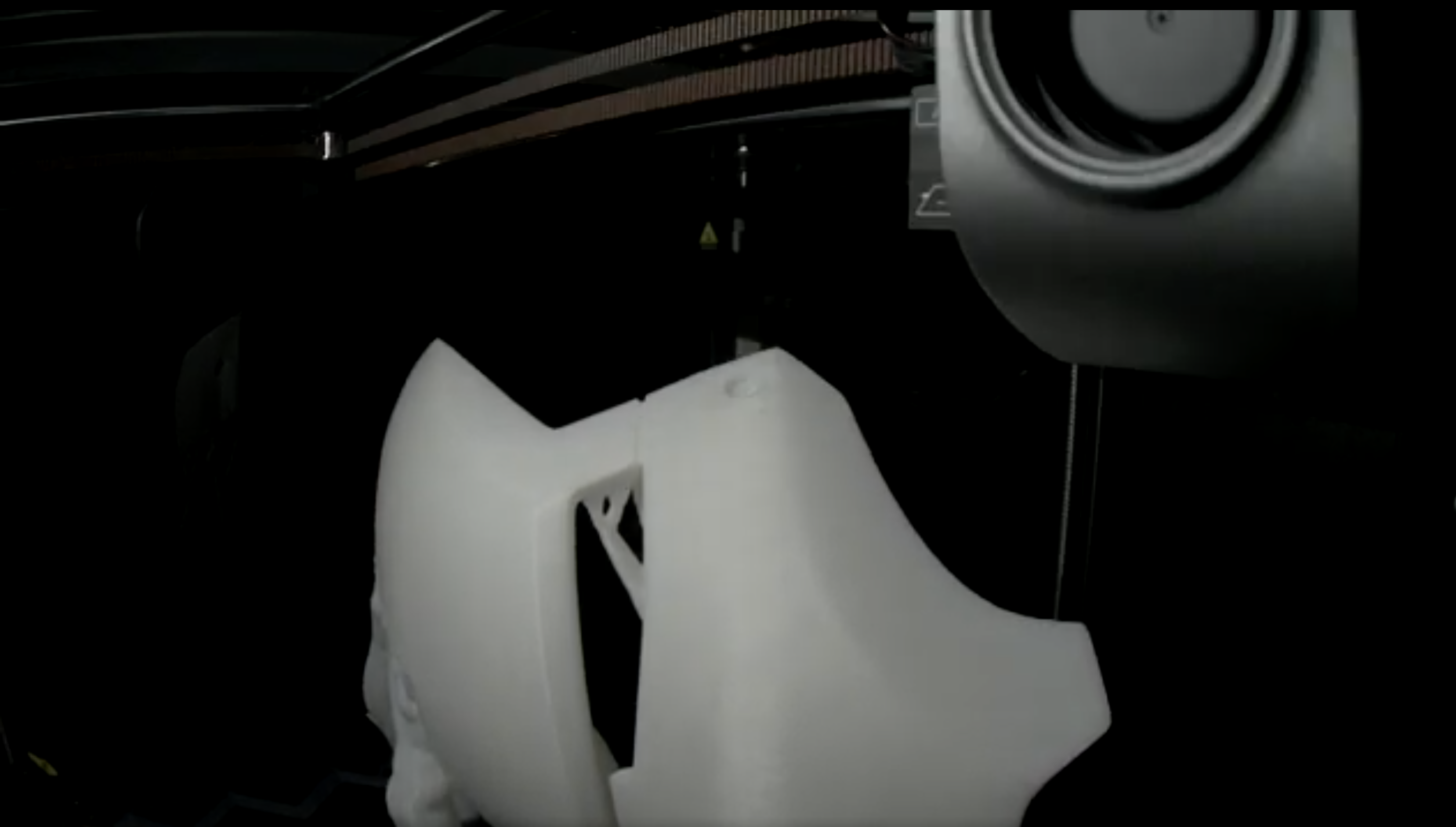
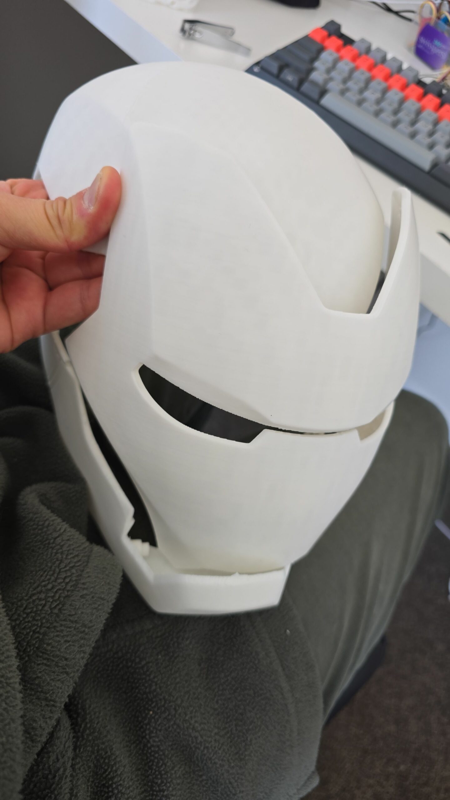
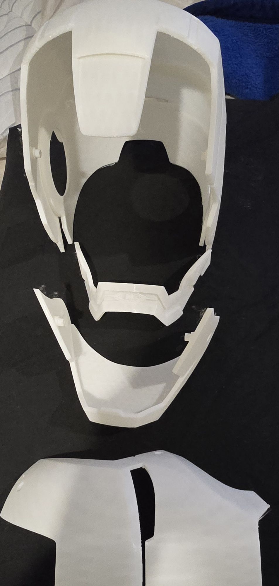
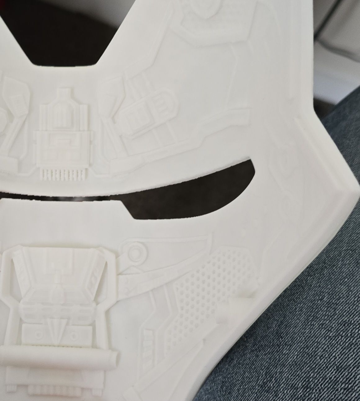
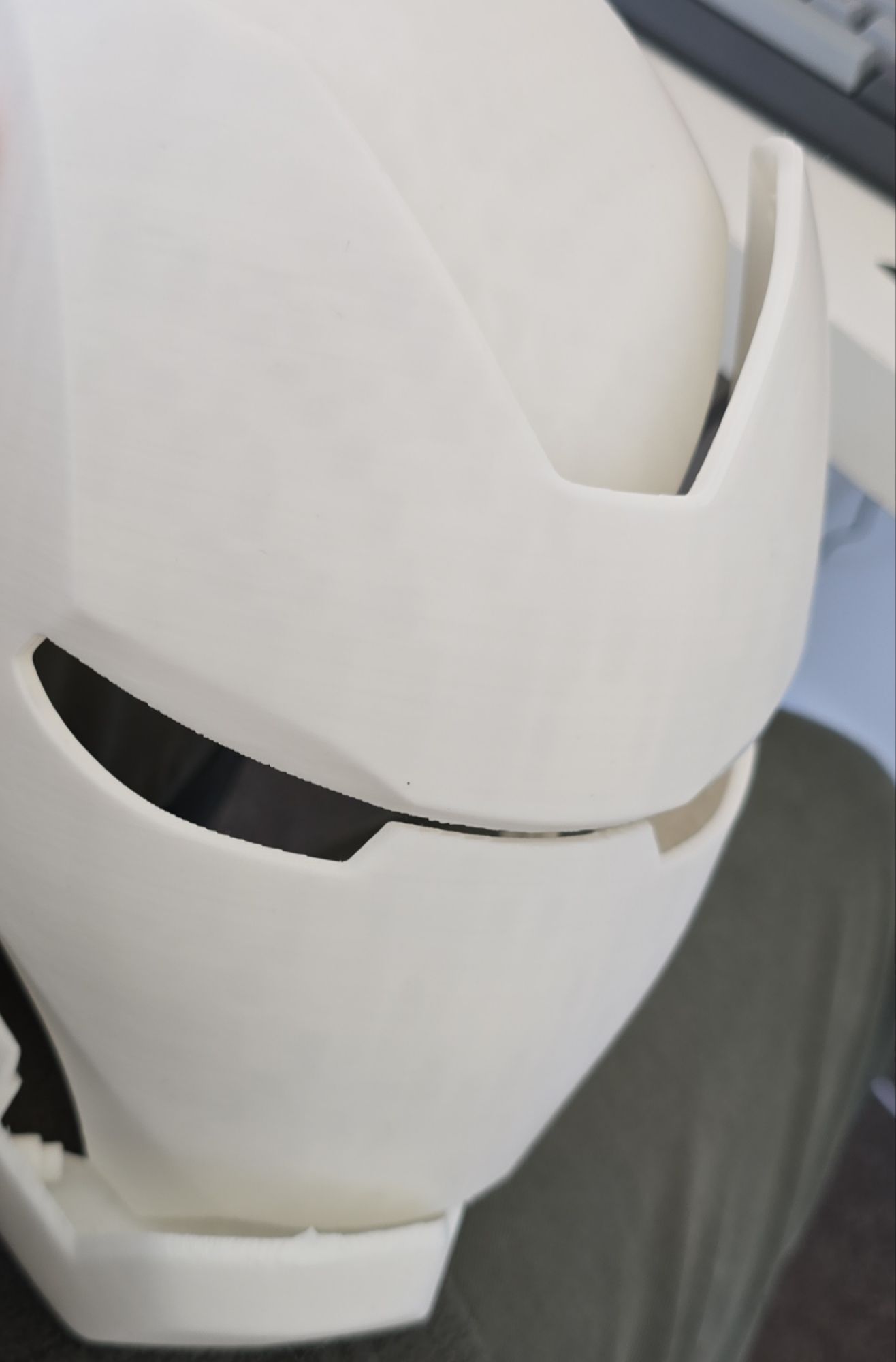
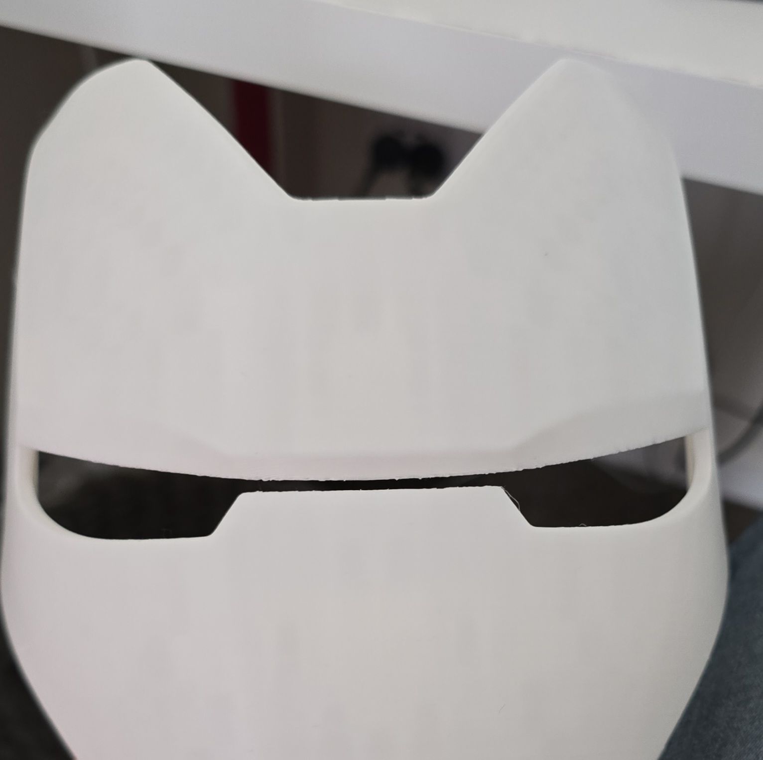
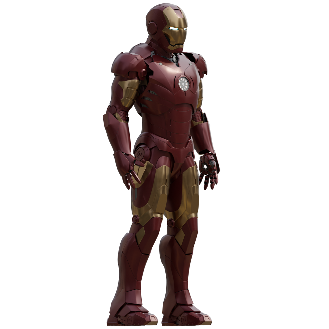
Iron Man Mark 3 Helmet
· One min read

3DPrinting
View All TagsBought the Iron Man Mark 3 3D Printing model designs from https://www.wf3d.shop/products/ironman-mark-3-suit-3d-printable-model by Walsh3D
Printed these so far:
This is the Part 4 and final blog of the series where I detail my journey in learning to build an IoT solution.
Please have a read of my previous blogs to get the full context leading up to this point before continuing.
I've always wanted to dip my toes into building IoT solutions beyond doing what a typical tutorial teaches in only turning on LEDs - I wanted to build something that would used everyday. Plus, I often forget to feed the cats while I am away from home (for the day), so it would be nice to come home to a non-grumpy cat by feeding them remotely any time and from any where in the world using the internet.
To simply describe what is built, the Feeder uses an Iot button click to trigger events over the internet to instruct the feeder to dispense food into one or both food bowls.
Here are some diagrams describing the architecture of the solution - the technical things that happens in-between the IoT button and the Cat Feeder.
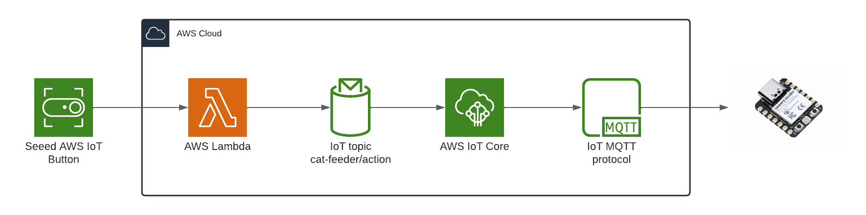
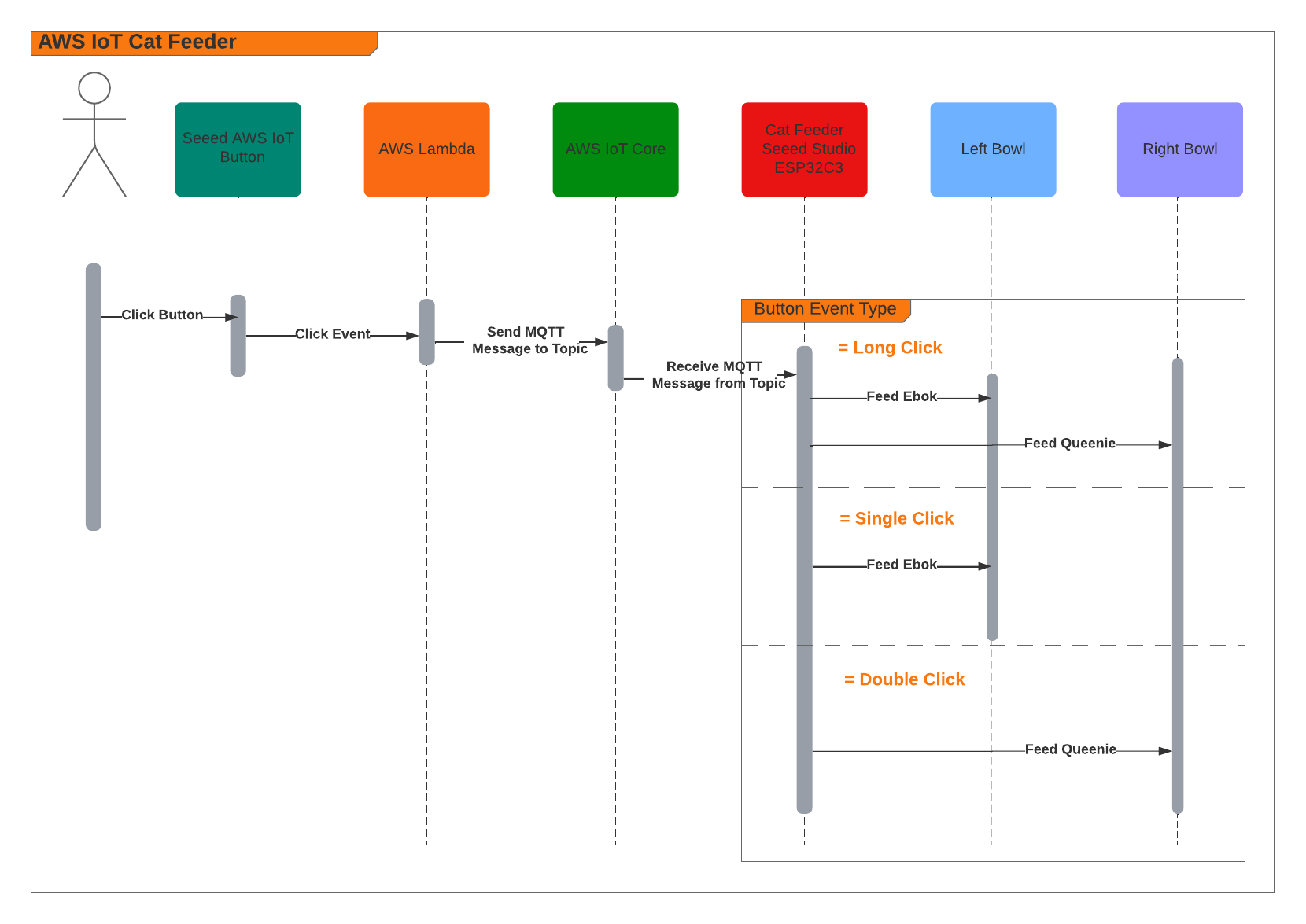
When the Feeder receives a MQTT message from the AWS IoT Core Service, it runs the motor for 10 seconds to dispense food into either one of food bowls, and if the message contains an event value to dispense food into both bowls we can run both motors concurrently using the L298N controller.
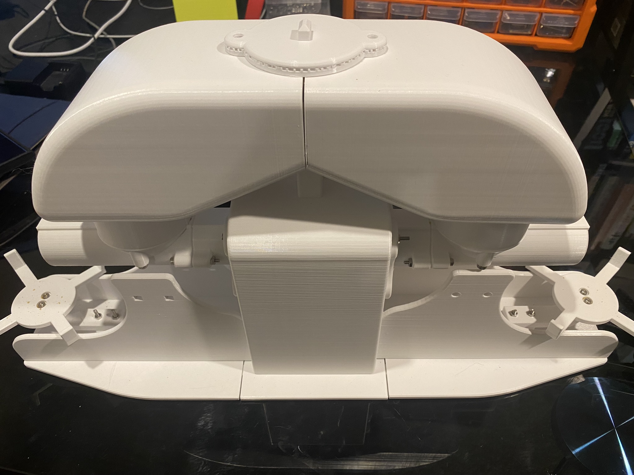
Here's a video of some timelapse picture captured during the 3 weeks it took to 3D print the feeder.
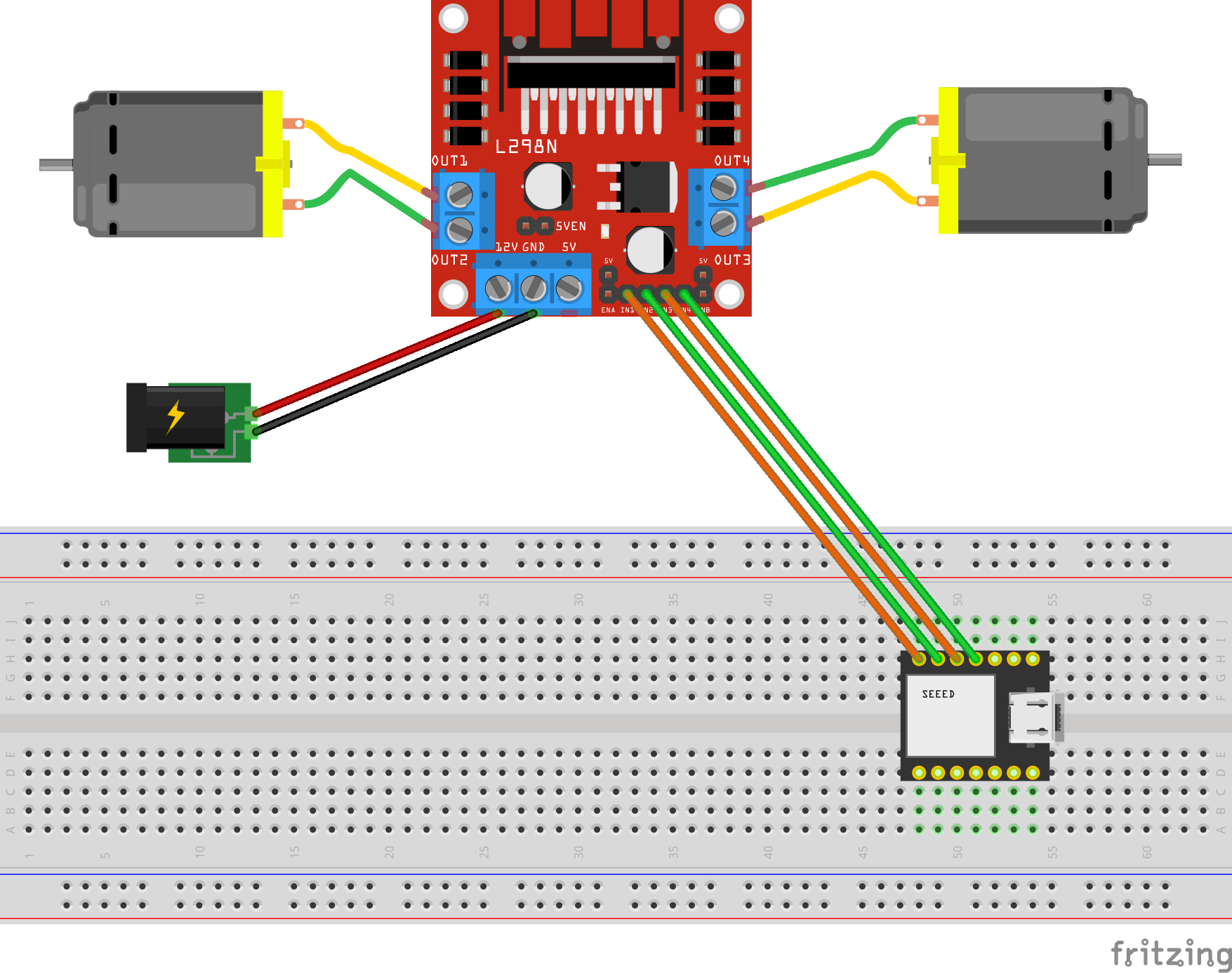
The Feeder is made up of a small handful of basic hardware components, below is a Breadboard diagram depicting the components used and how they are all wired up together. A regular 12V 2A DC power adapter supply is used to power all the components.
The code to start and stop a motor is about 10 lines of code as shown below. This is the completed version of the Arduino Sketch shown in Part 2 of this blog series when it was partially written at the time.
#include "secrets.h"
#include <WiFiClientSecure.h>
#include <MQTTClient.h>
#include <ArduinoJson.h>
#include "WiFi.h"

// The MQTT topics that this device should publish/subscribe
#define AWS_IOT_PUBLISH_TOPIC   "cat-feeder/states"
#define AWS_IOT_SUBSCRIBE_TOPIC "cat-feeder/action"

WiFiClientSecure net = WiFiClientSecure();
MQTTClient client = MQTTClient(256);

int motor1pin1 = 32;
int motor1pin2 = 33;
int motor2pin1 = 16;
int motor2pin2 = 17;

void connectAWS()
{
  WiFi.mode(WIFI_STA);
  WiFi.begin(WIFI_SSID, WIFI_PASSWORD);

  Serial.println("Connecting to Wi-Fi");
  Serial.println(AWS_IOT_ENDPOINT);

  while (WiFi.status() != WL_CONNECTED) {
    delay(500);
    Serial.print(".");
  }

  // Configure WiFiClientSecure to use the AWS IoT device credentials
  net.setCACert(AWS_CERT_CA);
  net.setCertificate(AWS_CERT_CRT);
  net.setPrivateKey(AWS_CERT_PRIVATE);

  // Connect to the MQTT broker on the AWS endpoint we defined earlier
  client.begin(AWS_IOT_ENDPOINT, 8883, net);

  // Create a message handler
  client.onMessage(messageHandler);

  Serial.println("Connecting to AWS IOT");
  Serial.println(THINGNAME);

  while (!client.connect(THINGNAME)) {
    Serial.print(".");
    delay(100);
  }

  if (!client.connected()) {
    Serial.println("AWS IoT Timeout!");
    return;
  }

  Serial.println("About to subscribe");
  // Subscribe to a topic
  client.subscribe(AWS_IOT_SUBSCRIBE_TOPIC);

  Serial.println("AWS IoT Connected!");
}

void publishMessage()
{
  StaticJsonDocument<200> doc;
  doc["time"] = millis();
  doc["state_1"] = millis();
  doc["state_2"] = 2 * millis();
  char jsonBuffer[512];
  serializeJson(doc, jsonBuffer); // print to client

  client.publish(AWS_IOT_PUBLISH_TOPIC, jsonBuffer);

  Serial.println("publishMessage states to AWS IoT" );
}

void messageHandler(String &topic, String &payload) {
  Serial.println("incoming: " + topic + " - " + payload);

  StaticJsonDocument<200> doc;
  deserializeJson(doc, payload);
  const char* event = doc["event"];

  Serial.println(event);

  feedMe(event);
}

void setup() {
  Serial.begin(9600);
  connectAWS();

  pinMode(motor1pin1, OUTPUT);
  pinMode(motor1pin2, OUTPUT);
  pinMode(motor2pin1, OUTPUT);
  pinMode(motor2pin2, OUTPUT);
}

void feedMe(String event) {
  Serial.println(event);

  bool feedLeft = false;
  bool feedRight = false;

  if (event == "SINGLE") {
    feedLeft = true;
  }
  if (event == "DOUBLE") {
    feedRight = true;
  }
  if (event == "LONG") {
    feedLeft = true;
    feedRight = true;
  }

  if (feedLeft) {
    Serial.println("run left");
    digitalWrite(motor1pin1, HIGH);
    digitalWrite(motor1pin2, LOW);
  }

  if (feedRight) {
    Serial.println("run right");
    digitalWrite(motor2pin1, HIGH);
    digitalWrite(motor2pin2, LOW);
  }

  delay(10000);
  digitalWrite(motor1pin1, LOW);
  digitalWrite(motor1pin2, LOW);
  digitalWrite(motor2pin1, LOW);
  digitalWrite(motor2pin2, LOW);
  delay(2000);

  Serial.println("fed");
}

void loop() {
  publishMessage();
  client.loop();
  delay(3000);
}
The Seeed AWS IoT Button is able to detect 3 different types of click events: Long, Single and Double, and we are able to leverage this all the way to the feeder so we will have it performing certains actions base on the click event type.
The video below demonstrates the following scenarios:
Build the nervous system of an ultimate nerd project I have in mind that would allow me to voice control actions controlling servos, LEDs and audio outputs, by using a mesh of Seeed XIAO BLE Sense micro-controllers and TinyML Machine Learning.
In this Part 3 of the blog series I talk about my experience printing objects using a 3D Printer for the first time. In Part 1, I talked about setting up an IoT Button; and in Part 2, I talked about publishing events to an Adruino Micro-controller from AWS.
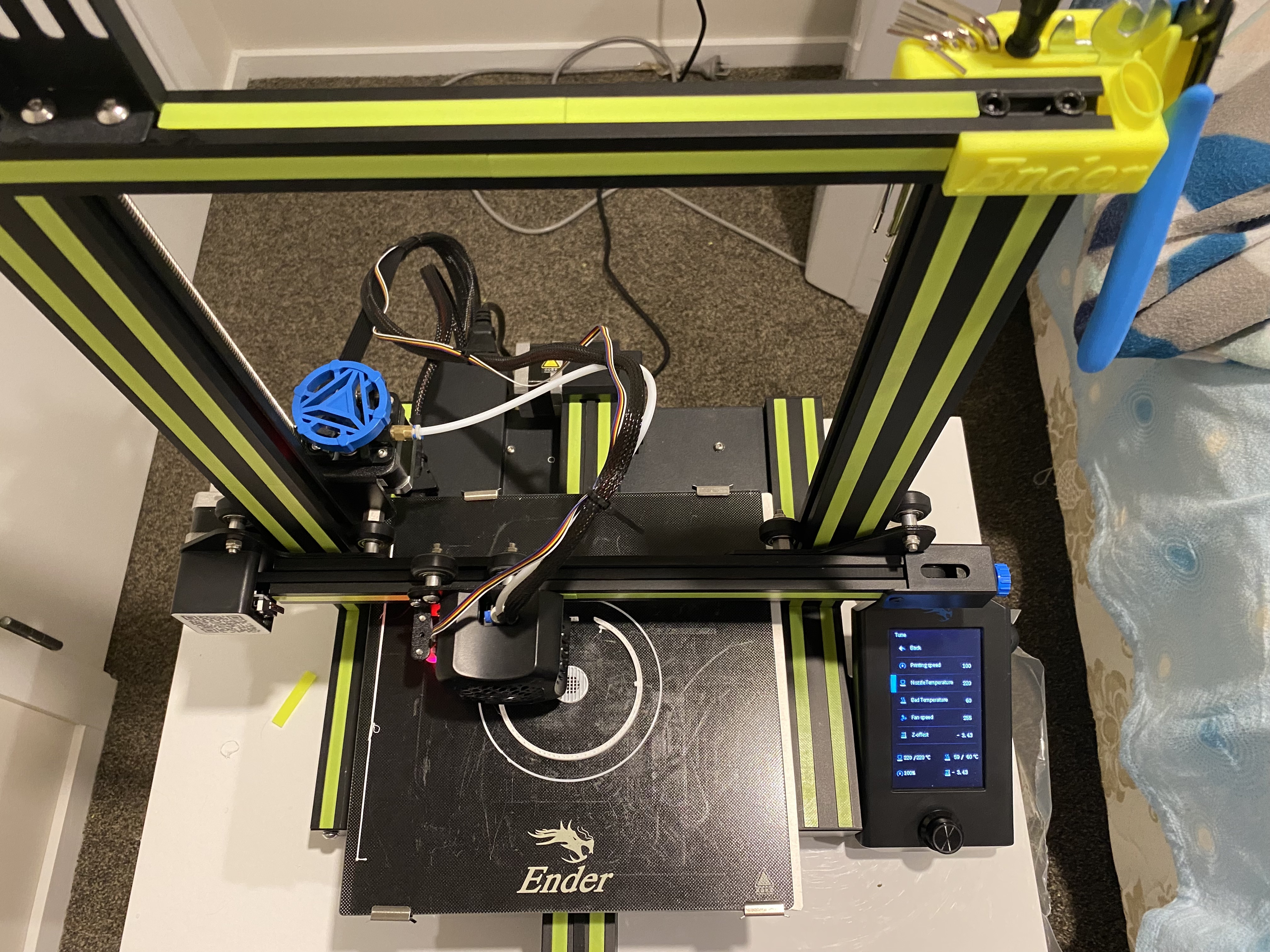
After putting in the hard work in setting up the Creality Ender 3 V2 3D printer, Queenie decided to give the BL Touch Auto Bed Levelling a test run. The Auto Levelling is a must as it greatly improvements productivity by not having to fiddle around with the bed as much without it.
Setting up the printer took 2 nights to set it up, a small portion of the effort was involved in physically putting all the printer parts together, but most of the time spent was fine tuning the Z axis (common problem) and levelling the bed - with prints we are working with margins of tolerances of 0.01mm in each of the 3 planes (X, Y and Z positions). I was lucky enough to avoid a lot of headache as a friend who has the same model had forewarned me of the common pain points in setting up this printer, so it would have taken a week or more to fine tune it if I had to figure it all out by myself.
There are loads of upgrade parts and accessories for the Creality Ender 3 which can be found on sites such as www.thingiverse.com published by the 3D printing community.
Turns out 3D modeling tools such as Blender is a lot more difficult to learn than I first anticipated; I originally set out to design a Cat Feeder model from scratch in Blender, however, the learning curve in picking it up is much stepper than I hoped; so I decided to jump on ThingieVerse and found a Cat Feeder designed shared by someone from the community. In future projects, I will be more strategic in what I decide build, I will focus on improving on the disciplines (AWS IoT, working with micro-controllers, sensors, motors, designing 3D models and printing plastics) where I need improvement the most. So the next project I have in mind is a Fish Feeder, the main goal of that is to improve my modeling skills, I will design an Feeder with way fewer and more simple components than this project but the core concept will remain the same. Fishes eat less than cats in terms of volume, which means I would be able to use a smaller single motor which in turns means a simpler controller/circuit and fewer parts, and potentially the feeder could run off a re-chargeable battery (charged via USB C) that could last roughly 6 months or more.
Here is what the printed parts look like.
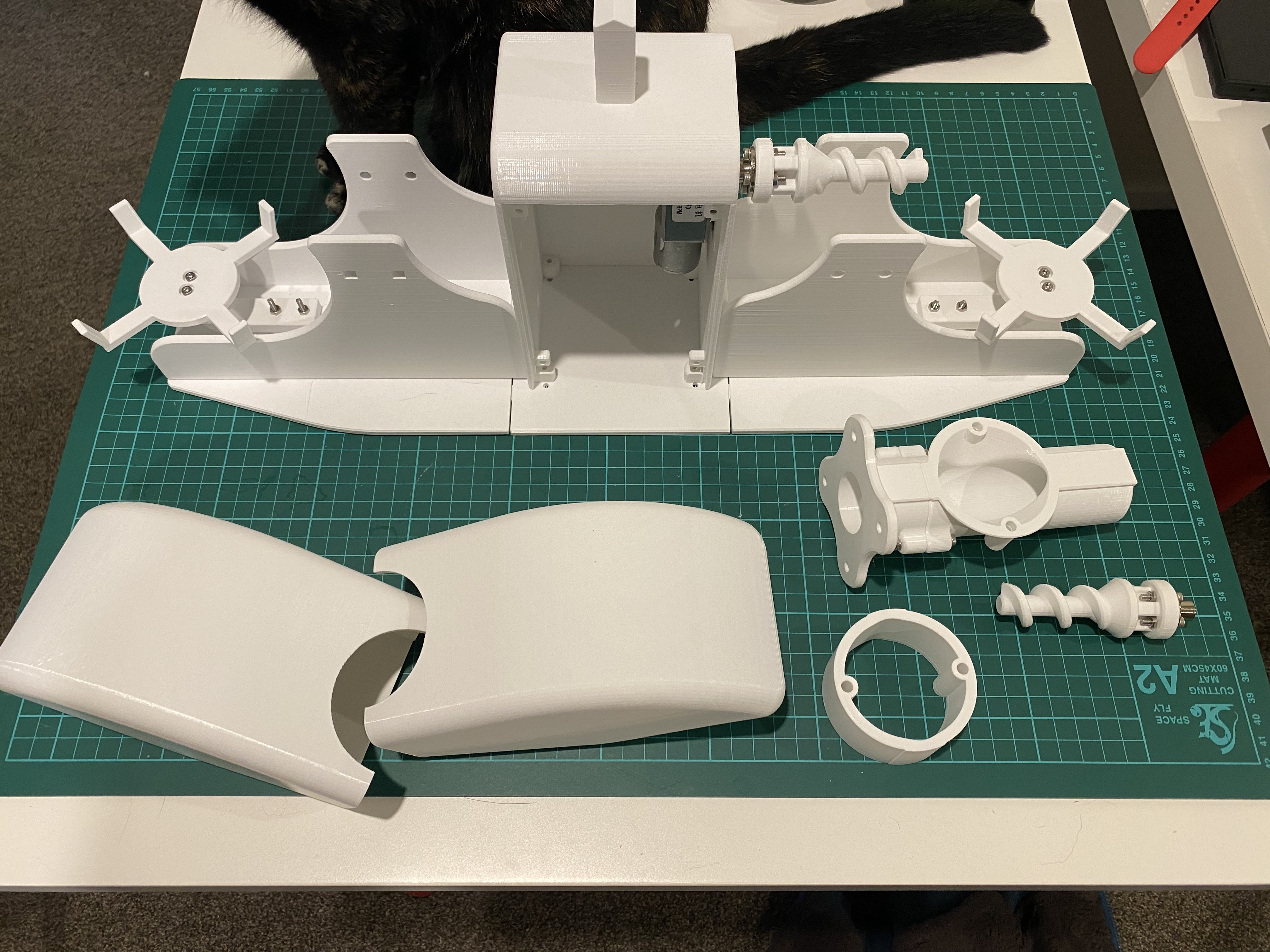
It took almost 4 weeks of constant printing, then half way through I remembered to create a time-lapse of the print.
I'm building this project with parts sourced from AliExpress to keep the cost of the build to a minimum but the down side to that means some parts takes months to arrive, I am waiting for the stepper motor controller and DC-DC step down (5.0V to 3.3V) power supply buck modules to arrive. Once the remaining parts arrive I will put together all the circuit components, followed by combining it with the bits from Part 1 and Part 2, then put out a final blog for the series with a demonstration.