AWS IoT Core – Iron Man – Part 1
· One min read

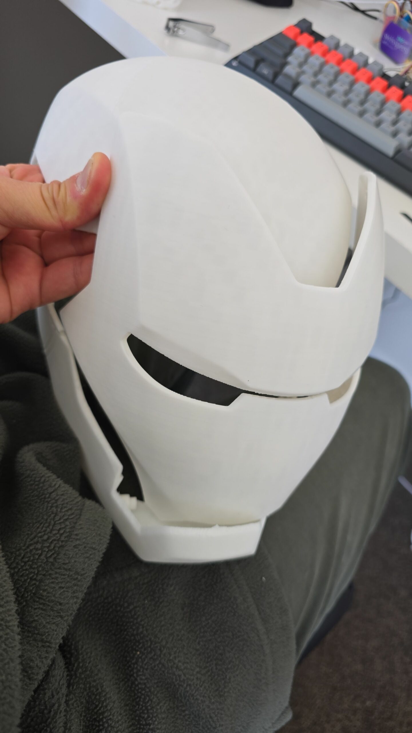
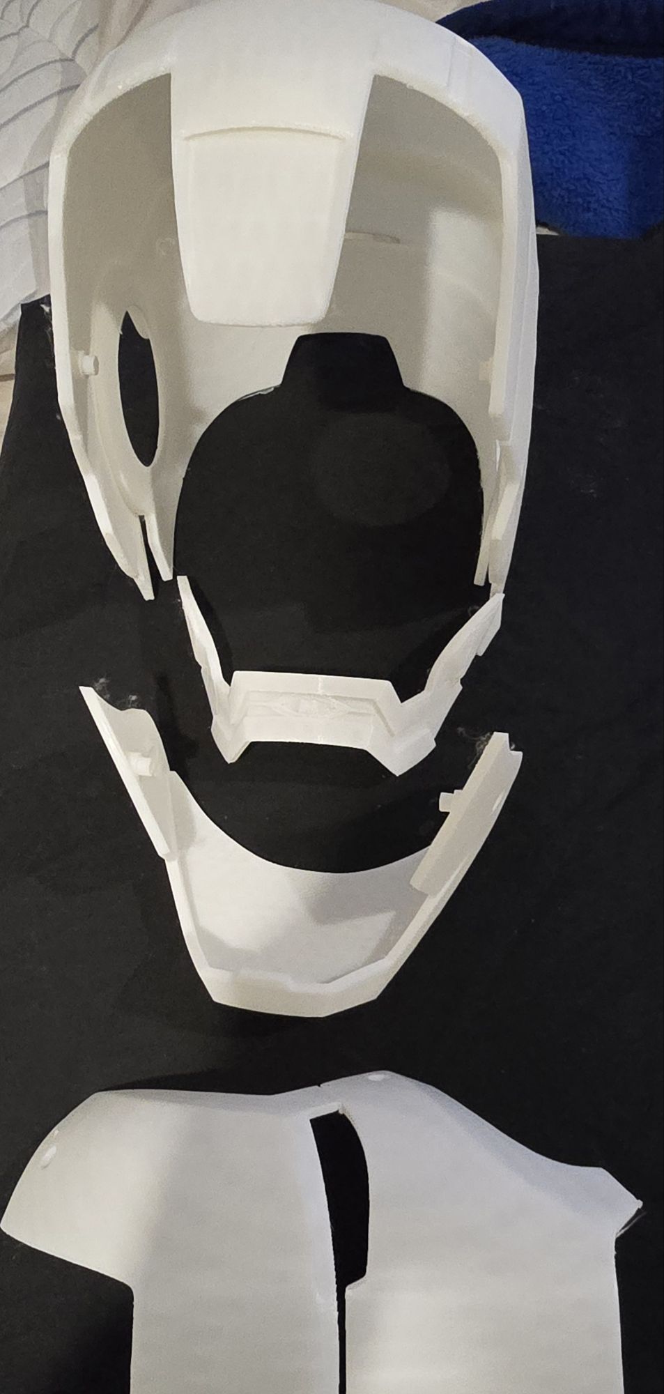
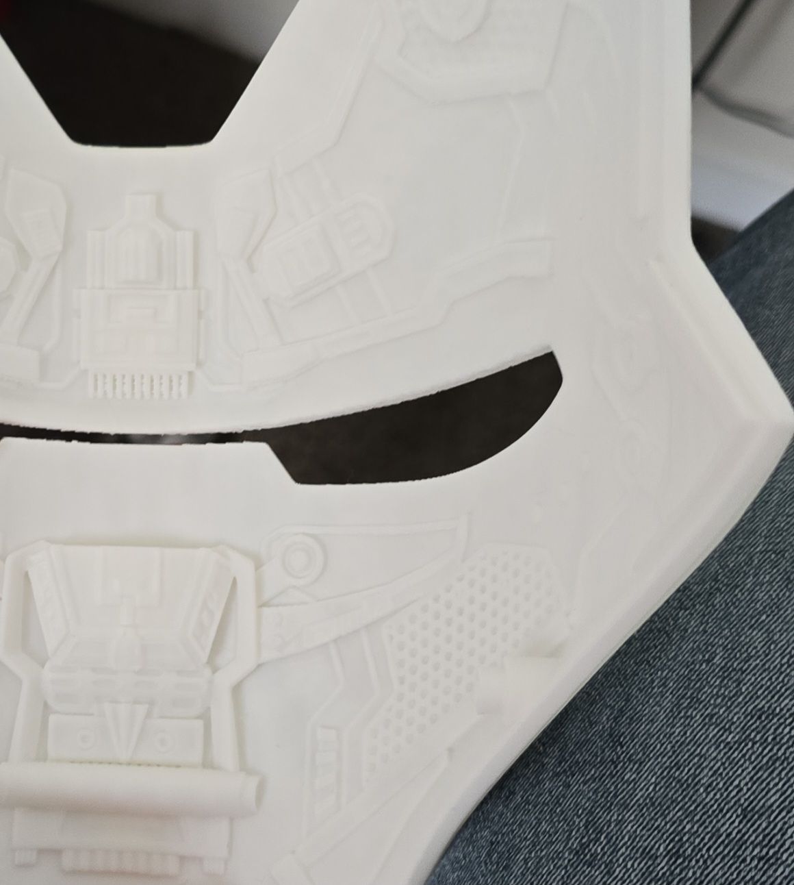
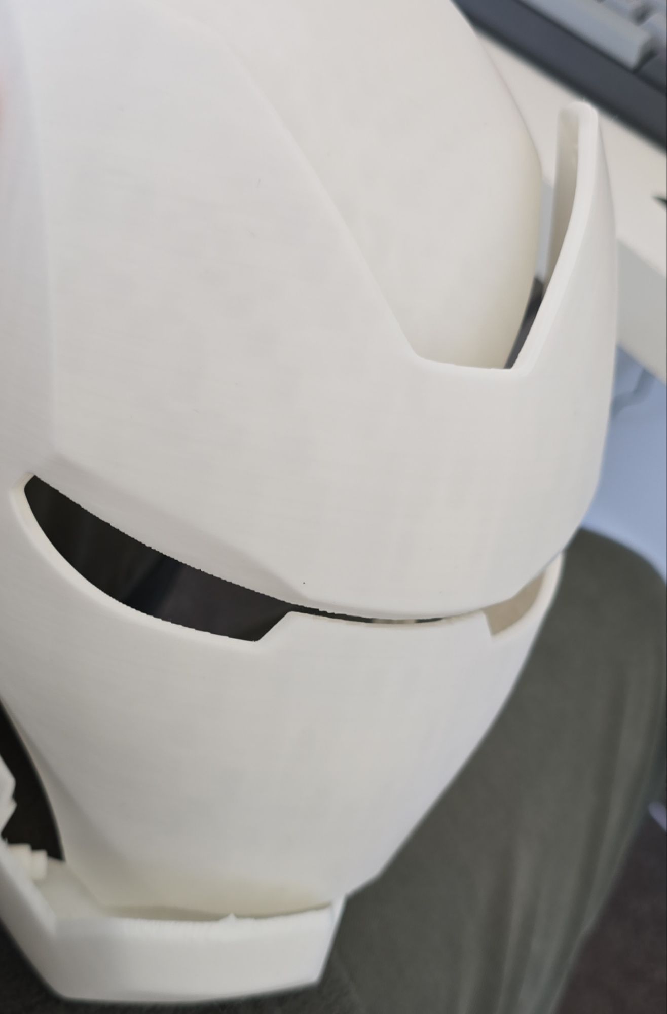
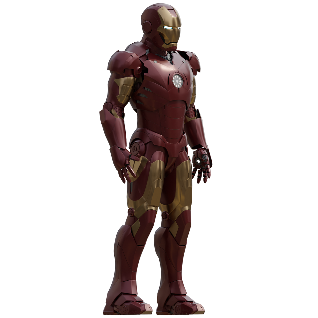
Bought the Iron Man Mark 3 3D Printing model designs from https://www.wf3d.shop/products/ironman-mark-3-suit-3d-printable-model by Walsh3D
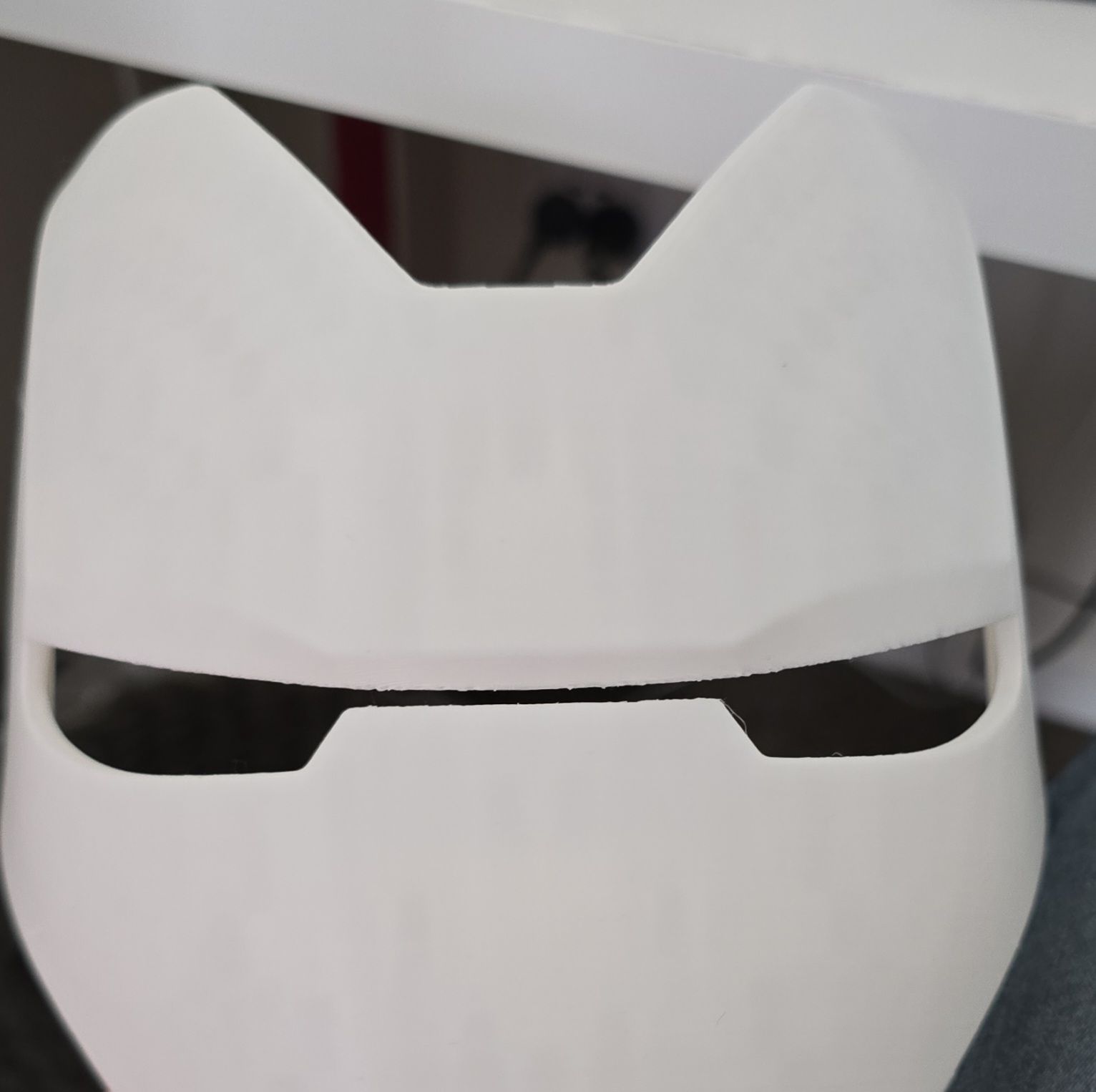
Printed these so far:
AWS
View All TagsBought the Iron Man Mark 3 3D Printing model designs from https://www.wf3d.shop/products/ironman-mark-3-suit-3d-printable-model by Walsh3D
Printed these so far:
In my code examples I shared in the past, when I sent and received IoT messages and states to and from AWS Core IoT Topics, I only implemented subscribers to react to perform a functionality when an MQTT message is received on a Topic; while that it was useful when my FurBaby was feed in the case when the Cat Feeder was triggered to drop Temptations into the bowls, however, we did not keep a record of the feeds or the State of the Cat Feeder into some form of data store over time - this meant we did not track when or how many times food was dropped into a bowl.
In this blog, I will demonstrate how to store the data in the MQTT messages sent to AWS IoT Core and ingest the data into Amazon Timestream database; Timestream is a serverless time-series database that is fully managed so we can leverage with worrying about maintaining the database infrastructure.
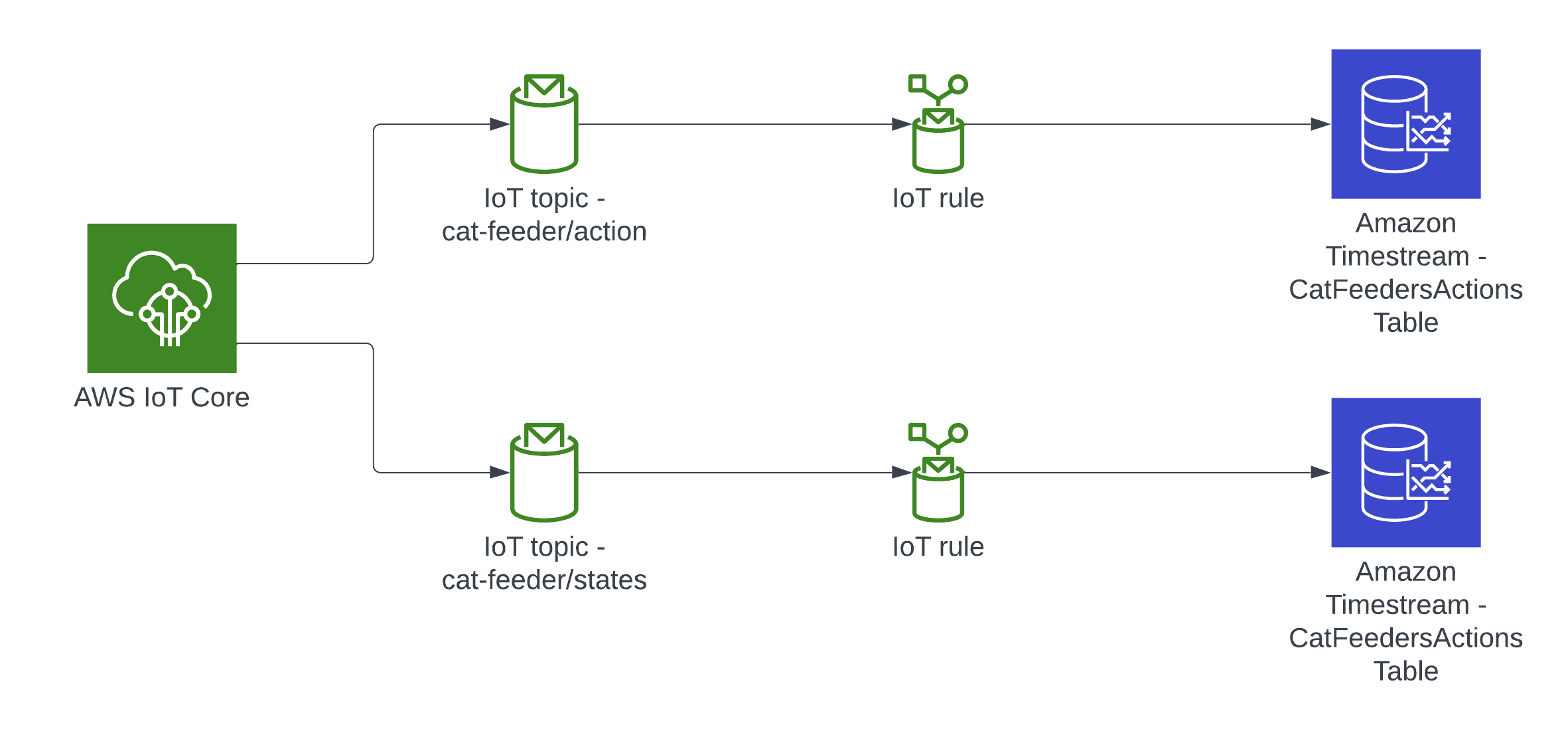
In this architecture we have two AWS IoT Core Topics, where each IoT Topic has an IoT Rule associated with it that will send all the data from every MQTT message receieved from that Topic - there is an ability to filter the messages but we've not using to use it, and that data is ingested into a corresponding Amazon Timestream table.
git clone git@github.com:chiwaichan/feedmyfurbabies-cdk-iot-timestream.git
cd feedmyfurbabies-cdk-iot-timestream
cdk deploy

git remote rm origin
git remote add origin https://git-codecommit.us-east-1.amazonaws.com/v1/repos/feedmyfurbabies-cdk-iot-timestream-FeedMyFurBabiesCodeCommitRepo
git push --set-upstream origin main
Here is a link to my GitHub repository where this reference architecture is hosted: https://github.com/chiwaichan/feedmyfurbabies-cdk-iot-timestream
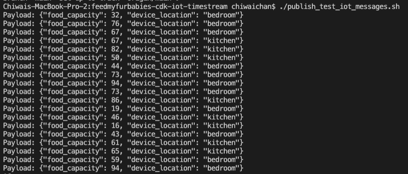
In the root directory of the repository is a script that simulates an IoT Thing and it will constantly publish MQTT messages to the "cat-feeder/states" Topic; ensure you have the AWS CLI installed on your machine with a default profile as it relies on it, and ensure the Access Keys used by the default profile has the permission to call "iot:Publish".
It sends a random number for the "food_capacity" that ranges 0-100 to represent the percentage of food that is remaining in a cat feeder, and a values for the "device_location" as we are scaling out with the number of cat feeders placed around the house. Be sure to send the same JSON structure in your MQTT message if you decide to not use the provided script to send the messages to the Topic.
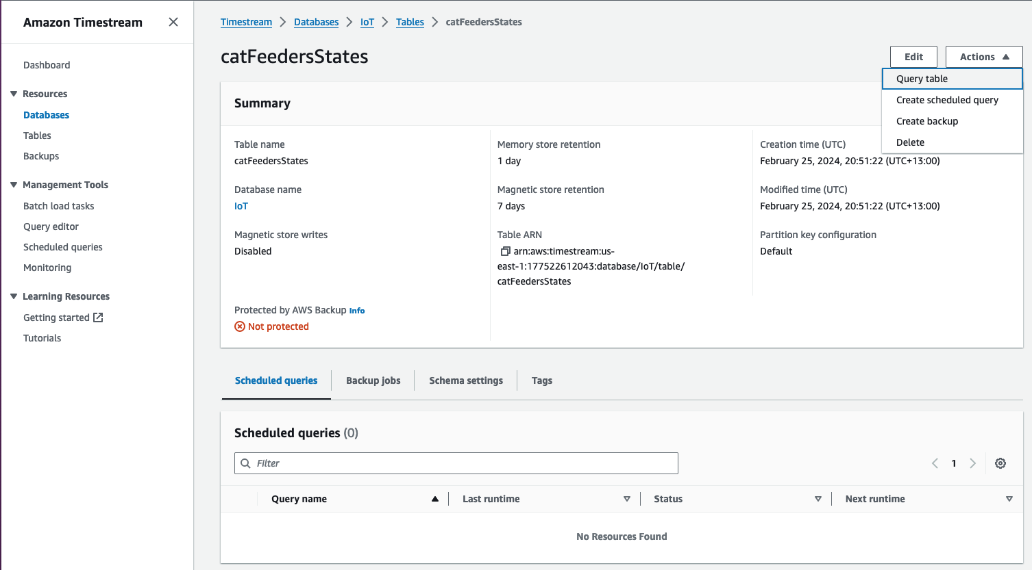
Now lets jump into the AWS Console, then jump into the Timestream Service and go into the "catFeedersStates" Table; then click on "Actions" to show the "Query table" option to go to the Query editor.
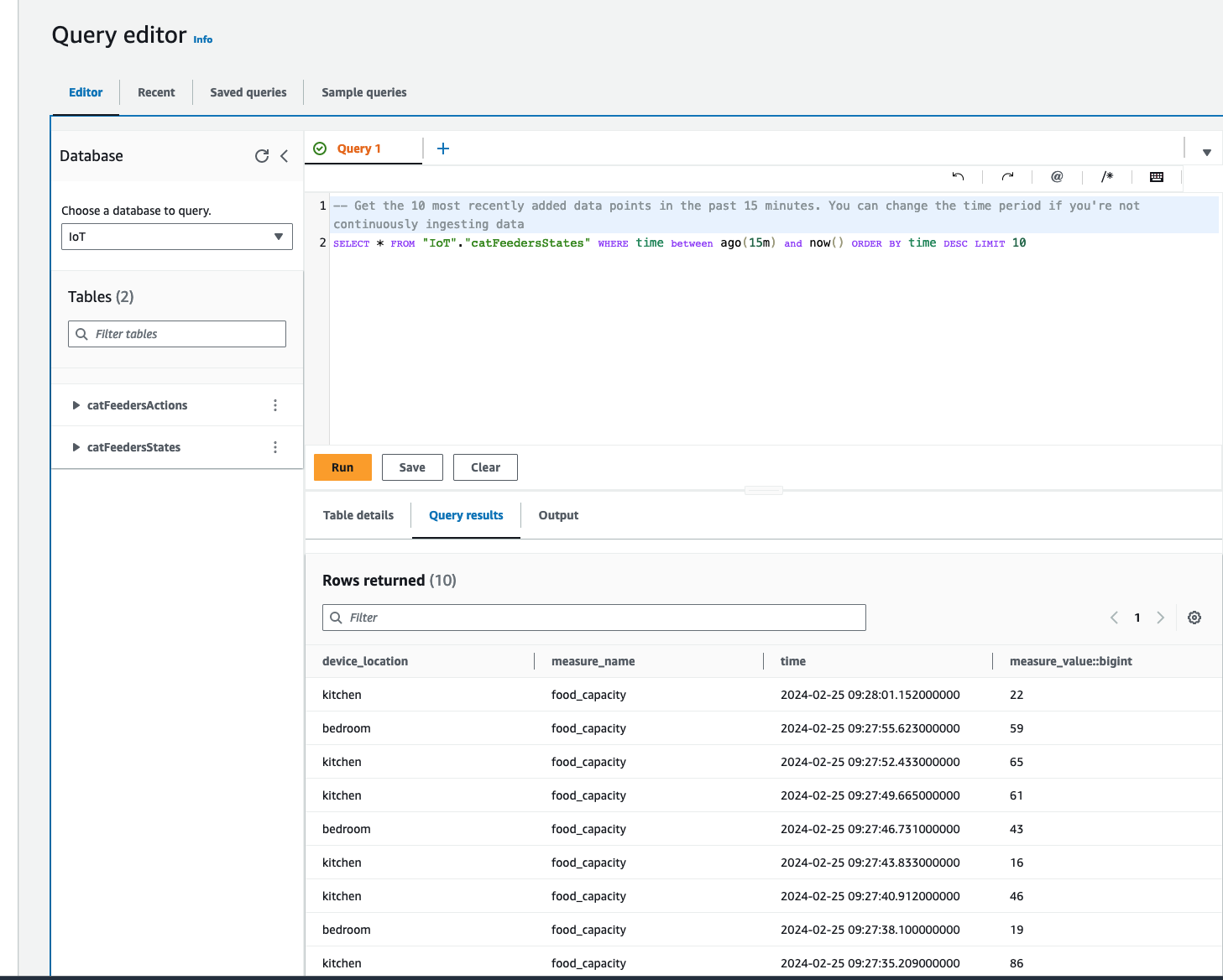
The Query editor will show a default query statement, click "Run" and you will see in the Query results the data from the MQTT messages that was generated by the script; where the MQTT messages was ingested from the IoT Topic "cat-feeder/states".
Recently I switched my Cat Feeder project's IaC to AWS CDK in favour of increasing my focus and productivity on building and iterating, rather than constantly mucking around with infrastructure everytime I resume my project after a break; which is rare and far between these days.
Just as with coding IoT microcontrollers such as the ESP32s, I want to get straight back into building every opportunity I get; so I am also switching away from Arduino based microcontroller development written in C++ - I don't have a background in C++ and to be honest this is the aspect I struggled with the most because I tend to forget things after not touching it for 6 months or so.
So I am switching to MicroPython to develop the logic for all my IoT devices going forward, this means I get to use Python - a programming lanaguge I work with frequently so there is less chance of me being forgetful when I use it at least once a month. MicroPython is a lean and efficient implementation of the Python 3 programming language that includes a subset of the Python standard library and is optimized to run on microcontrollers and in constrained environments - a good fit for IoT devices such as the ESP32!
Good news is MircoPython is supported on all ESP32 devices - based on the ones I myself have purchased; all I need to do to each ESP32 device is to flash it with a firmware - if you are impatient, you can scroll down and skip to below to the flashing the firmware section. When I first started Arduino, MicroPython was available to use, but that was 2 years ago and there were not as many good blog and tutorial content out there as there is today; I couldn't at the time work out how to control components such as sensors, servos and motors as well as I could with C++ based coding using Arduino; nowdays there are way more content to learn off and I've learnt (by PoCing individual components) enough to switch to MicroPython. As far as I understand it, any components you have for Arduino can be used in MicroPython, provided that there is a library out there that supports it, if there isn't then you can always write your own!
By the end of this blog, you will be able to send and receive MQTT messages from AWS IoT core using MicroPython, I will also cover the steps involved in flashing a MicroPython firmware image onto an ESP32C3. Although this blog has a focus and example on using an ESP32, this example can be applied to any micro-controllers of any brand or flavours, provided the micro-controller you are using supports MicroPython.
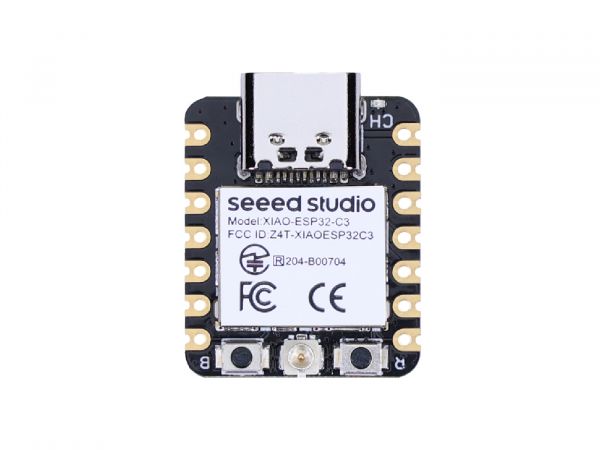
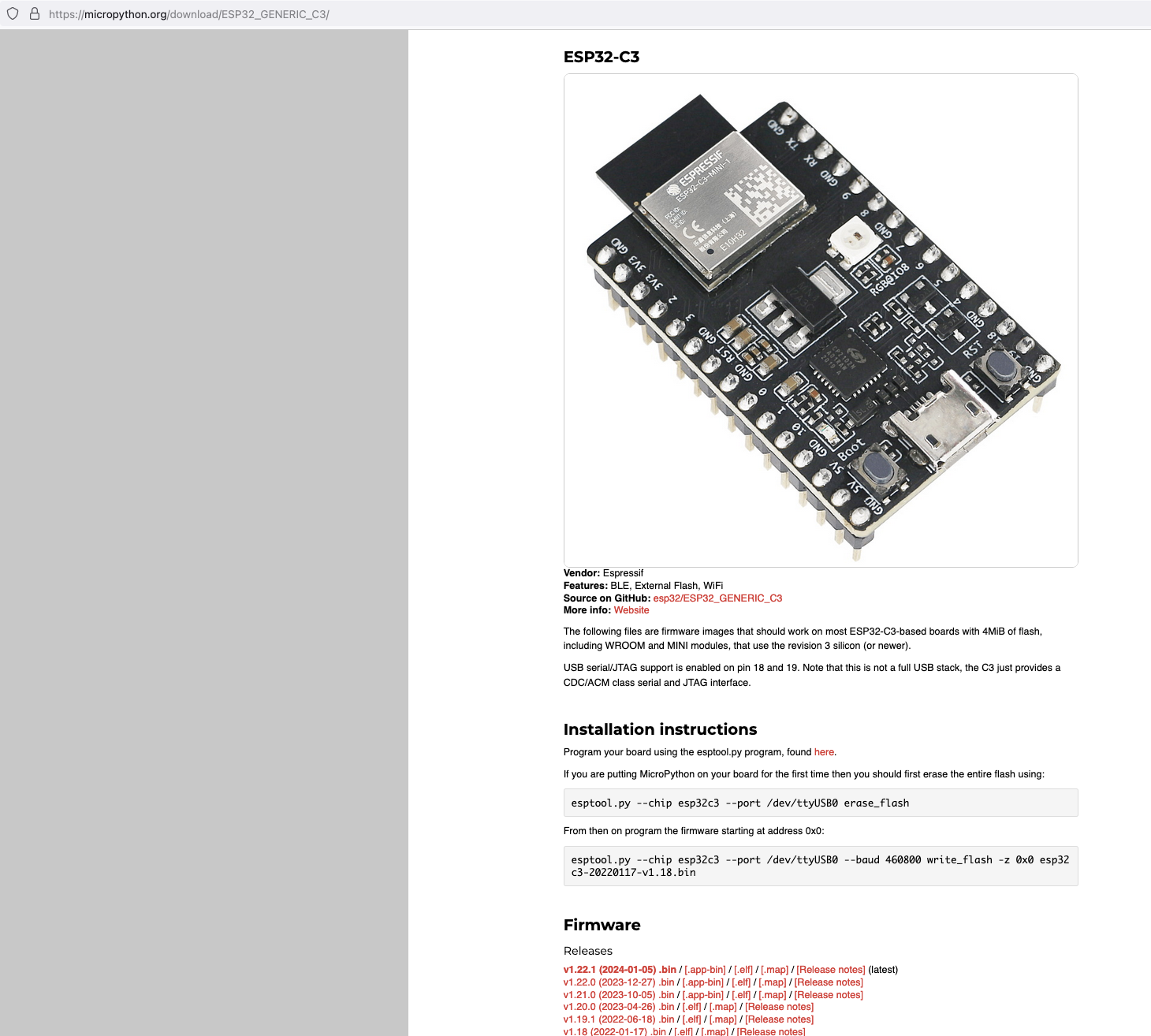
The following instructions works for any generic ESP32C3 devices!
https://micropython.org/download/ESP32_GENERIC_C3/
Next, I connected my ESP32C3 to my Mac and ran the following command to find the name of the device port
/dev/ttyUSB0

My ESP32C3 is named "/dev/tty.usbmodem142401", the name for your ESP32C3 may be different.
Next, install esptool onto your computer, then run the following commands to flash the MicroPython firmware onto the ESP32C3 using the bin file you've just downloaded.
esptool.py --chip esp32c3 --port /dev/tty.usbmodem142401 erase_flash

esptool.py --chip esp32c3 --port /dev/tty.usbmodem142401 --baud 460800 write_flash -z 0x0 ESP32_GENERIC_C3-20240105-v1.22.1.bin
It should look something like this when you run the commands.
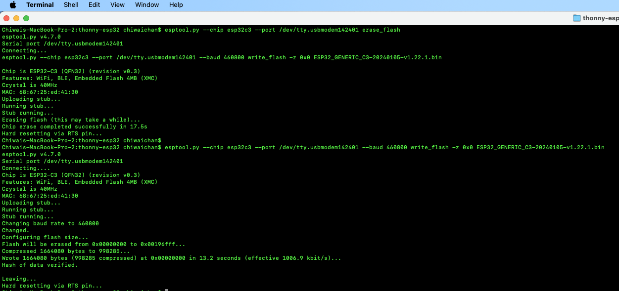
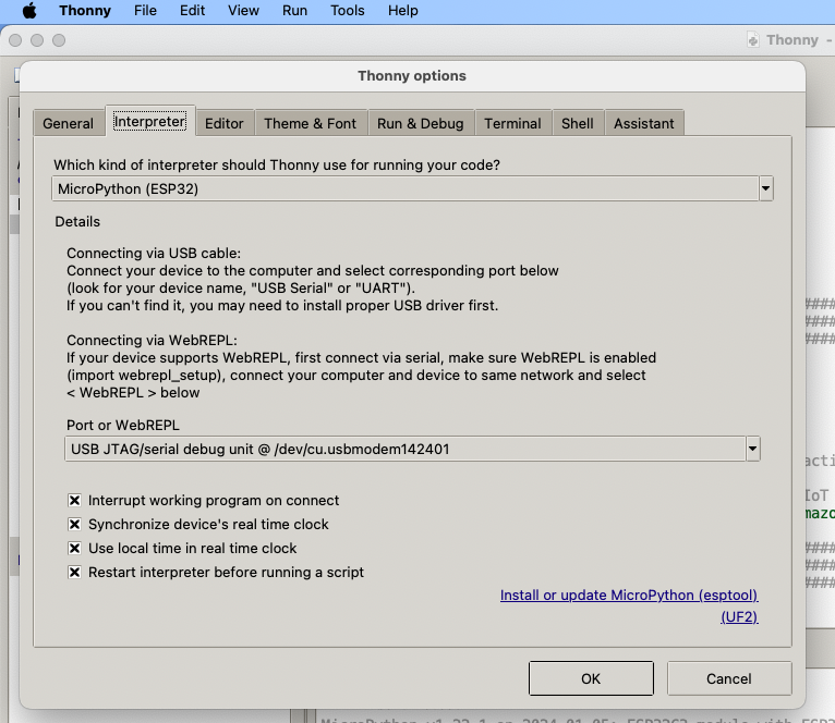
Install Thonny and run it. Then go to Tools -> Options, to configure the ESP32C3 device in Thonny to match the settings shown in the screenshot below.
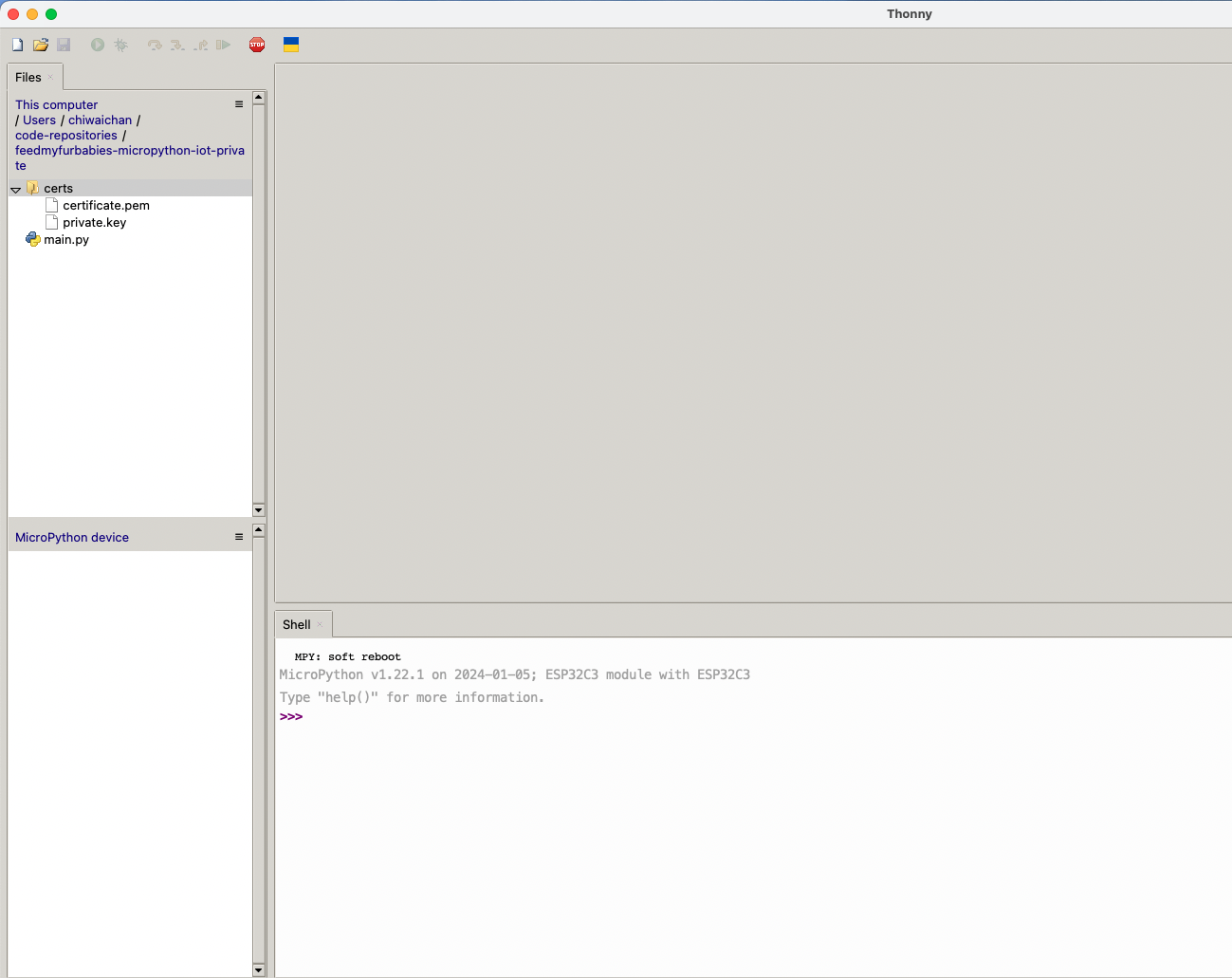
If everything went well, you should see these 2 sections in Thonny: "MicroPython Device" and "Shell", if not then try clicking on the Stop button in the top menu.
In order to send MQTT messages to an AWS IoT Core Topic, or to receive a message from a Topic in reverse, you will need a set of Certificate and Key\s for your micro-controller; as well as the AWS IoT Endpoint specific to your AWS Account and Region.
It's great if you have those with you so you can skip to the next section, if not, do not worry I've got you covered. In a past blog I have a reference architecture accompanied by a GitHub repository on how to deploy resources for an AWS IoT Core solution using AWS CDK, follow that blog to the end and you will have a set of Certificate and Key to use for this MicroPython example; the CDK Stack will deploy all the neccessary resources and policies in AWS IoT Core to enable you to both send and receive MQTT messages to two separate IoT Topics.
Reference AWS IoT Core Architecture: https://chiwaichan.co.nz/blog/2024/02/02/feedmyfurbabies-i-am-switching-to-aws-cdk/
Now lets upload the MicroPython code to your micro-controller and prepare the IoT Certificate and Key so we can use it to authenticate the micro-controller to enable it to send and receive MQTT messages between your micro-controller and IoT Core.
Clone my GitHub repository that contains the MicroPython example code to publish and receive MQTT message with AWS IoT Core: https://github.com/chiwaichan/feedmyfurbabies-micropython-iot
It should look something like this.
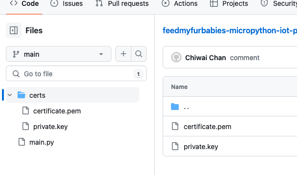
Copy your Certificate and Key into the respective files shown in the above screenshot; otherwise, if you are using the Certificate and Key from my reference architecture, then you should use the 2 Systems Manager Parameter Store values create by the CDK Stack.

Next we convert the Certificate and Key to DER format - converting the files to DER format turns it into a binary format and makes the files more compact, especially neccessary when we run use it on small devices like the ESP32s.
In a terminal go to the certs directory and run the following commands to convert the certificate.pem and private.key files into DER format.
openssl rsa -in private.key -out key.der -outform DER
openssl x509 -in certificate.pem -out cert.der -outform DER
You should see two new files with the DER extension appear in the directory if all goes well; if not, you probably need to install openssl.

In Thonny, in the Files explorer, navigate to the GitHub repository's Root directory and open the main.py file. Fill in the values for the variables shown in the screenshot below to match your environment, if you are using my AWS CDK IoT referenece architecture then you are only required to fill in the WIFI details and the AWS IoT Endpoint specific to your AWS Account and Region.
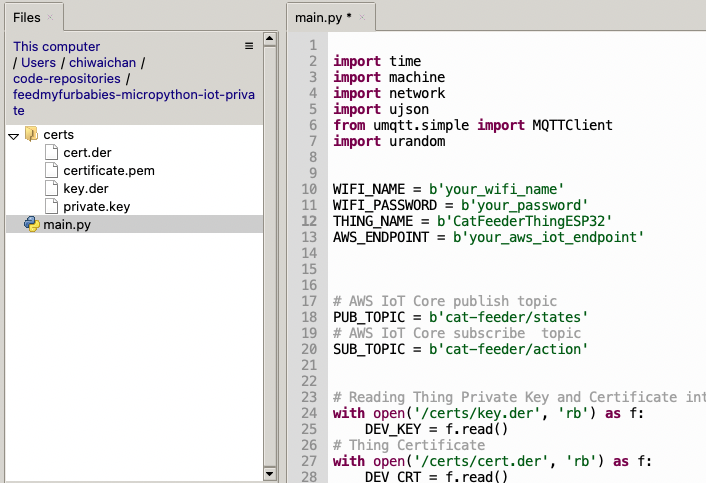
Select both the certs folder and main.py in the Files explorer, then right click and select "Upload to /" to upload the code to your micro-controller; the files will appear in the "MicroPython Device" file explorer.
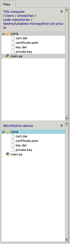
This is the moment we've been waiting for, lets run the main.py Python script by clicking on the Play Icon in green.
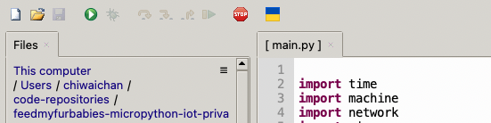
If all goes well you should see some output in the Shell section of Thonny.
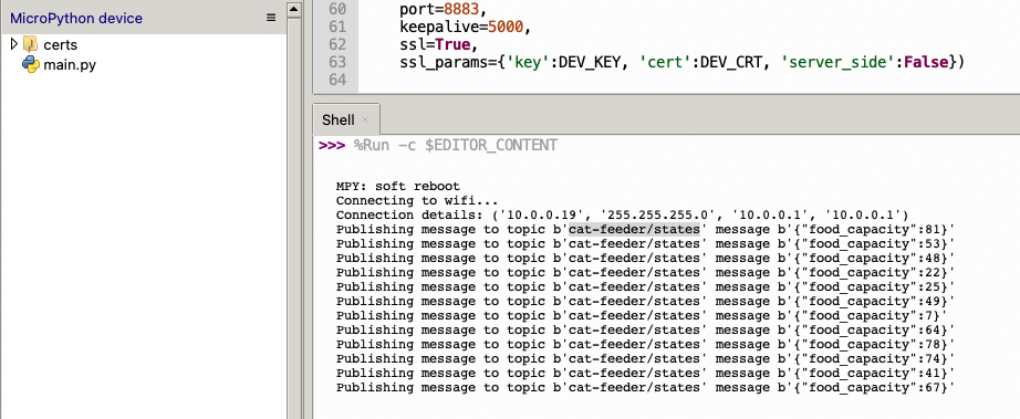
The code in the main.py file has a piece of code that is generating a random number for the food_capacity percentage property in the MQTT message; you can customise the message to fit your use case.
But lets verify it is actually received by AWS IoT Core.
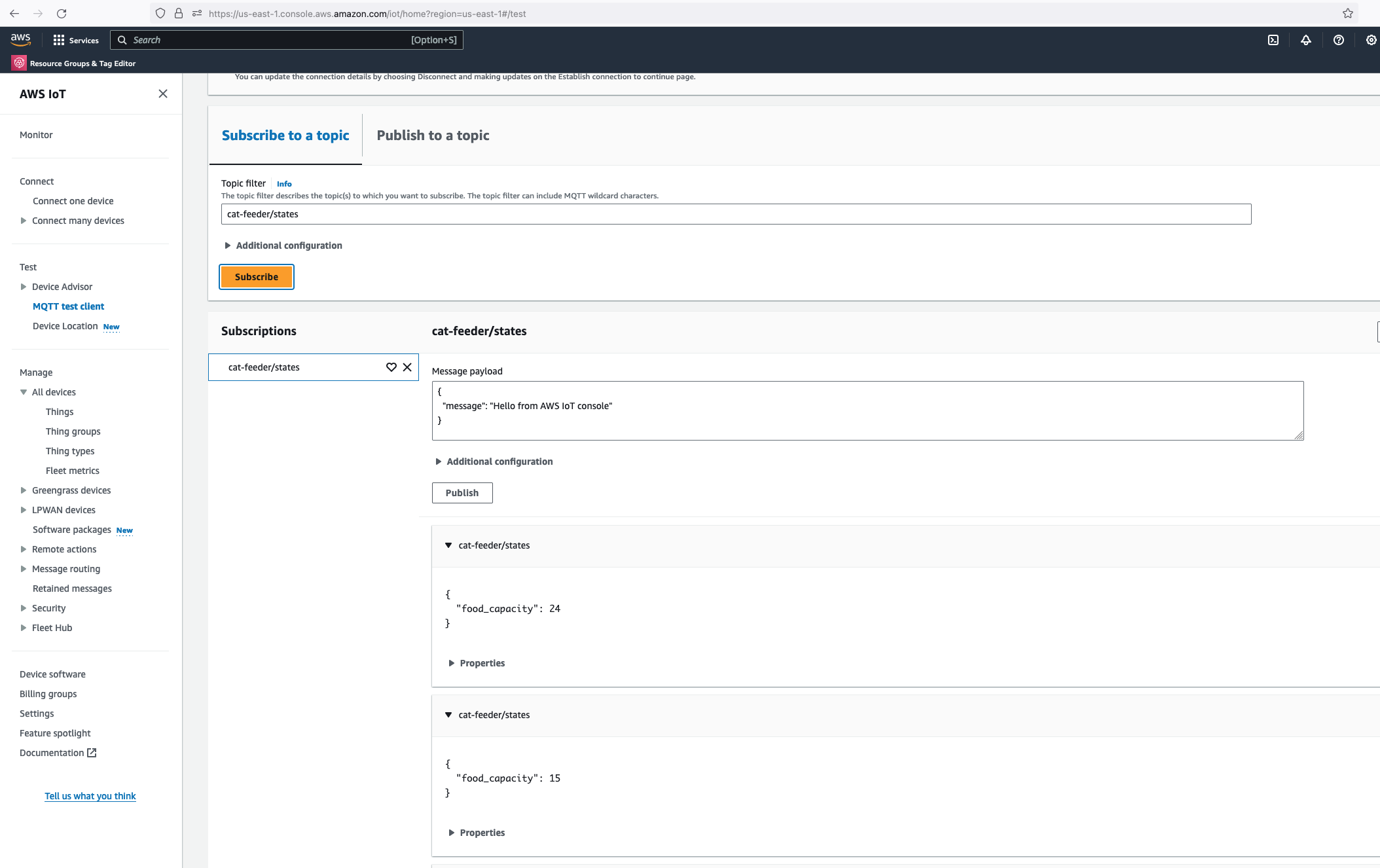
Alright, lets go the other way and see if we can receive MQTT messages from AWS IoT Core using the other Topic called "cat-feeder/action" we subscribed to in the MicroPython code.
Lets go back the AWS Console and use the MQTT test client to publish a message.
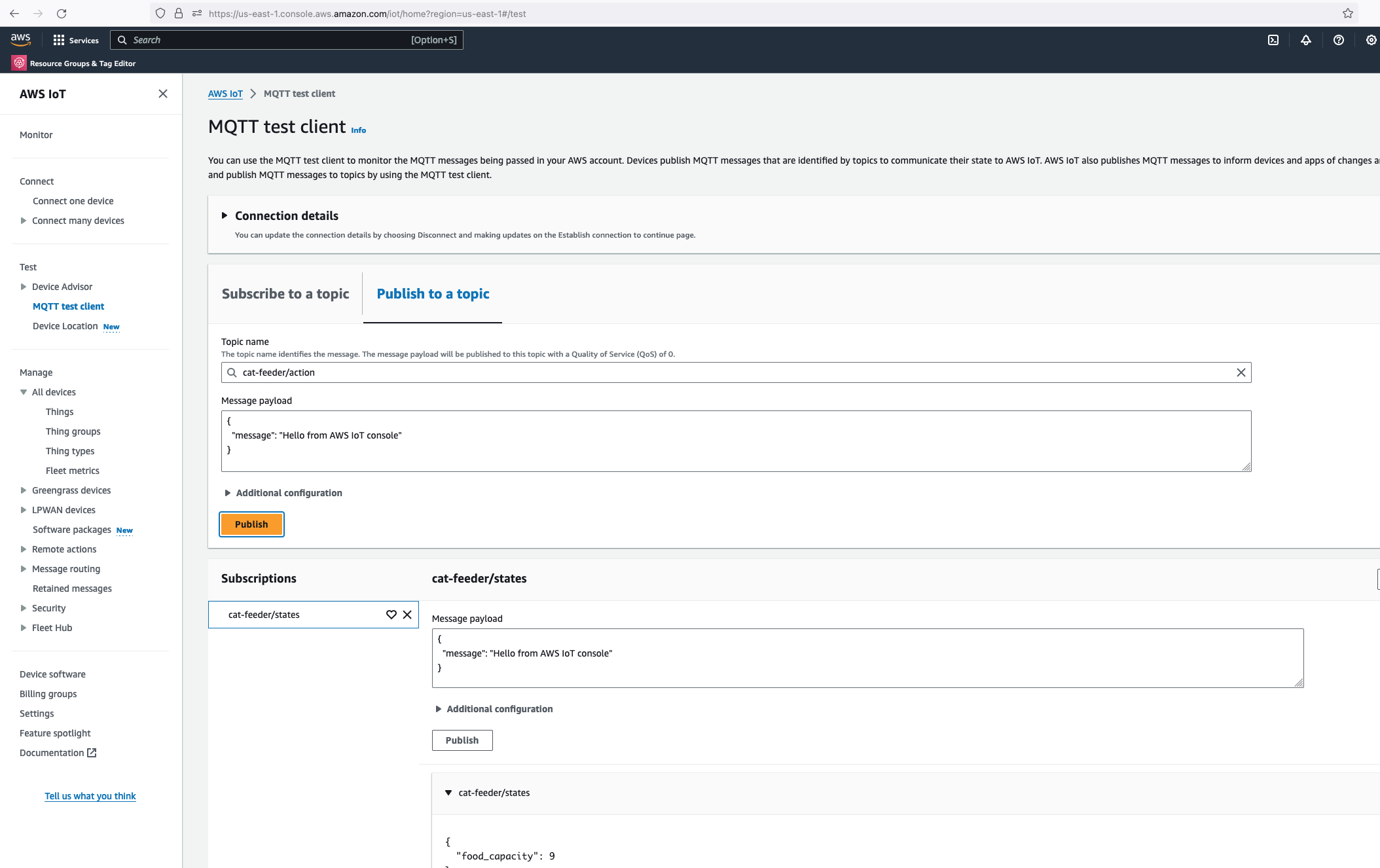
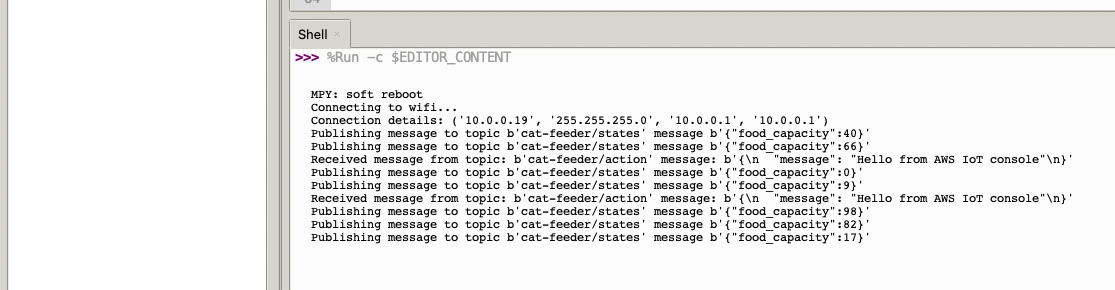
In the Thonny Shell we can see the message "Hello from AWS IoT console" sent from the AWS IoT Core side and it being received by the micro-controller.
It is real.
I'm starting a new blog series where I will be documenting my build of a full-stack Web and Mobile application using AWS Amplify to implement both the frontend, as well as the backend; whilst developing dependent downstream Services outside of Amplify using AWS Serverless components to implement a Micro-Service architecture using Event-Driven design pattern - where we will break the application up into smaller consumable chunks that works together well.
Since we are creating from scratch a completely new application, I will also incorporate a vital pattern that will reduce complexity throughout the lifetime of the application: we will also be implementing the application using the Event-Sourcing pattern - this pattern ensures every Event ever published within a system is stored within an immutable ledger; this ledger will enable new Data Stores of any Data Store Engine to be created at any given time by replaying the Events in the ledger, of Events created from a start date and time to an end Date and Time.
CQRS is a pattern I will write up about with great detailed in a blog in the near future, CQRS will enable the ability to create mulitple Data Stores with identical data, each Data Store using a unique Data Store Engine instance.
Amplify is an AWS Service that provides any frontend web or mobile developers with no cloud expertise the ability to build and host full-stack applications on AWS. As a frontend developer, you can leverage it to build and integrate AWS Services and components into your frontend without having to deal with the underlying AWS Services; all Services the frontend is built on top of is managed by AWS Amplify - e.g. no need to managed CloudFormation Stacks, S3 Storage or AWS Cognito.
My experience from a while ago was full-stack application development and I have worked under that role for over 10 years, I've used various frontend/backend frameworks, components and patterns.
I will be building a website called Feed My Fur Babies where I will provide video streams showing live feeds of my cats from web cams placed in various spots around my house, the website will also provide users with the ability to feed my cats using internet enabled devices like the IoT Cat Feeders I recently put together and watch them hoon on their favorite treats; although I am experienced with building websites from the ground up using AWS Service, I am aiming to build Feed My Fur Babies whilst leveraging as little as possible on that experience - this is so I am building the website as close to the targeted demographics skillset of a typical Amplify as possible, i.e. as a developer with only frontend experience.
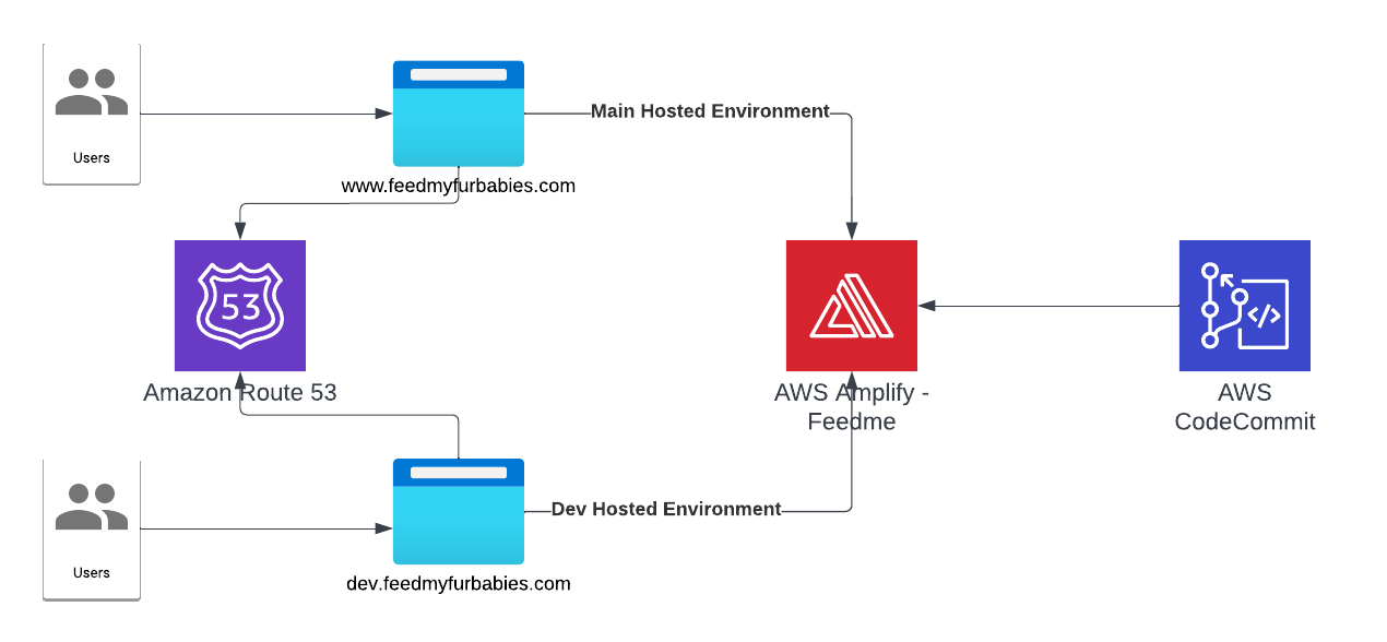
Let's talk about what was done to get to the current architecture state.
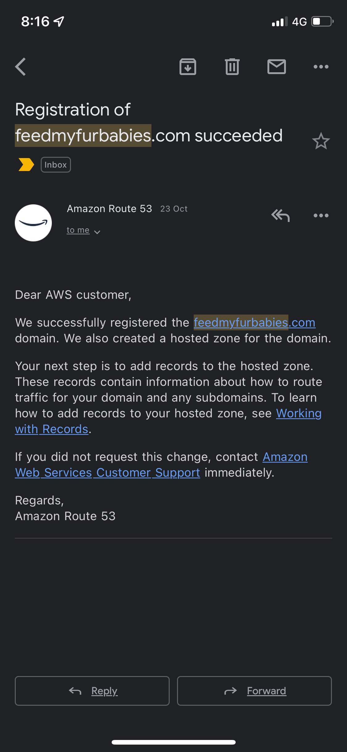
First thing I did was buying the domain feedmyfurbabies.com using AWS Route53.
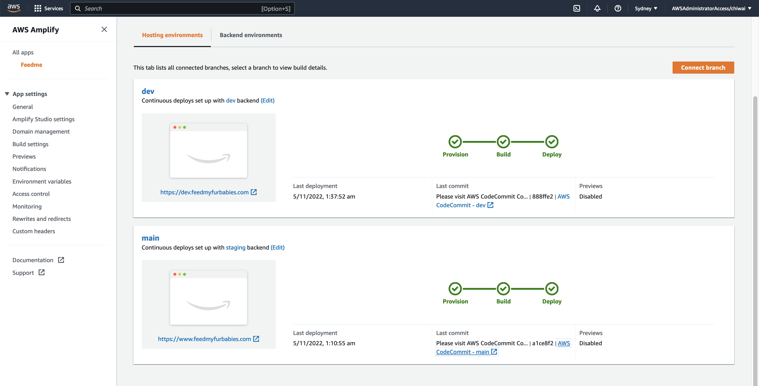
Next, I created a new Amplify App called "Feedme".

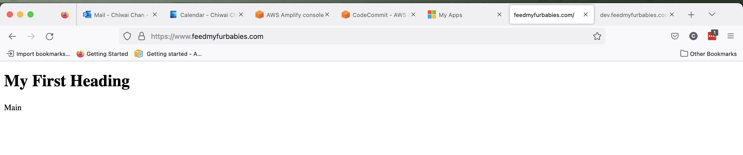
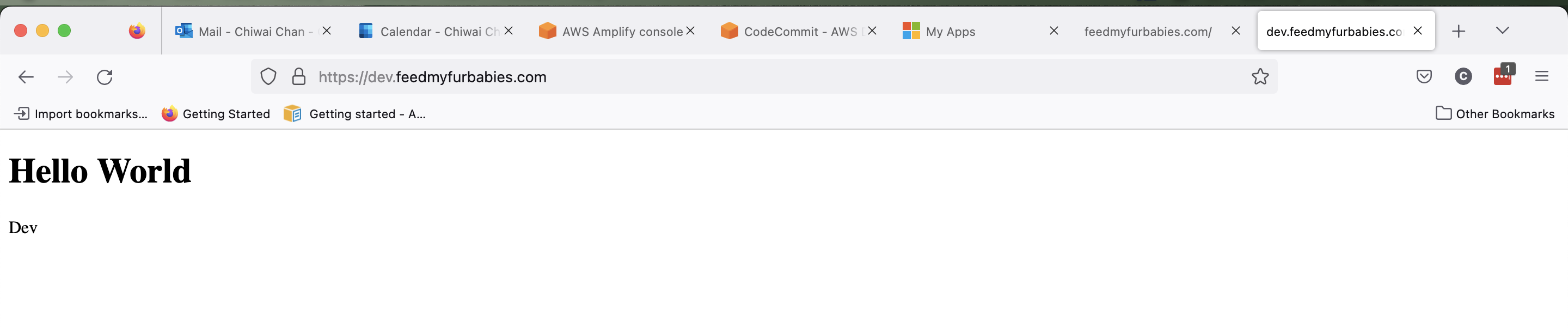
Within the App I created two Hosted Environments: one environment is to host the production environment, the other is to host a development environment. Each Hosted Environment is configured to be built and deployed from a specfic Branch in the shared CodeCommit Repository used to version control the frontend source code.
This blog is to detail my first experiences with AWS DeepRacer as somebody who knows very little about how AI works under the hood, and at first didn't fully understand the difference between Supervised Learning vs Unsupervised Learning vs Reinforcement Learning when I was writing my first Python code for the "reward_function".
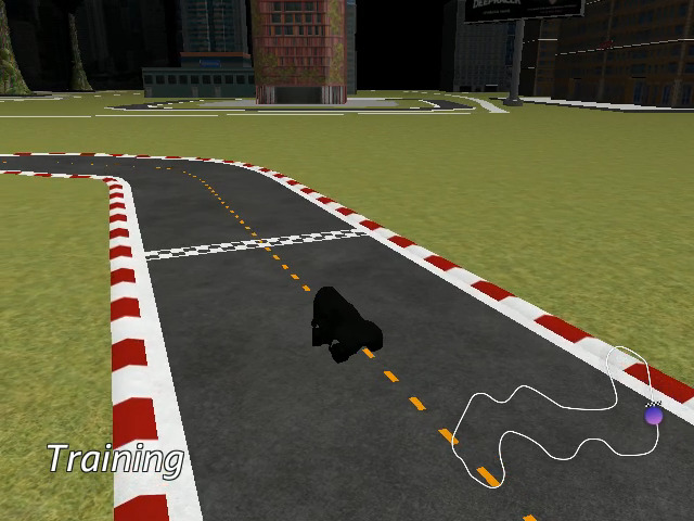
DeepRacer is a Reinforcement Learning based AWS Machine Learning Service that provides a quick and fun way to get into ML by letting you build and train an ML model that can be used to drive around on a virtual, as well as a physical race track.
I'm a racing fan in many ways whether it is watching Formula 1, racing my mates in go karting or having a hoon on the scooter, so once I found out about AWS DeepRacer service I've always wanted to dip my toes in it. More than 2 years later I found an excuse to play with it during my preparations for the AWS Certified Machine Learning Specialty exam, I am expecting a question or two on DeepRacer in the exam so what better way to learn about DeepRacer than to try it out by cutting some Python code.
Have a realistic one this time and keep it simple: produce an ML model that can drive a car around a few diferent virtual tracks for a few laps without going off the track.
Code a Python Reward Function to return a Reinforcement Reward value based on the state of the DeepRacer vehicle - the reward can be positive for good behaviour and also be negative to discourage the agent (vehicle) for a state that is not going to give us a good race pace. The state of the vehicle is a set of key/values shown below and is available to the Python Reward Function during runtime for us to use to calculate a reward value.
    # "all_wheels_on_track": Boolean,        # flag to indicate if the agent is on the track
    # "x": float,                            # agent's x-coordinate in meters
    # "y": float,                            # agent's y-coordinate in meters
    # "closest_objects": [int, int],         # zero-based indices of the two closest objects to the agent's current position of (x, y).
    # "closest_waypoints": [int, int],       # indices of the two nearest waypoints.
    # "distance_from_center": float,         # distance in meters from the track center
    # "is_crashed": Boolean,                 # Boolean flag to indicate whether the agent has crashed.
    # "is_left_of_center": Boolean,          # Flag to indicate if the agent is on the left side to the track center or not.
    # "is_offtrack": Boolean,                # Boolean flag to indicate whether the agent has gone off track.
    # "is_reversed": Boolean,                # flag to indicate if the agent is driving clockwise (True) or counter clockwise (False).
    # "heading": float,                      # agent's yaw in degrees
    # "objects_distance": [float, ],         # list of the objects' distances in meters between 0 and track_length in relation to the starting line.
    # "objects_heading": [float, ],          # list of the objects' headings in degrees between -180 and 180.
    # "objects_left_of_center": [Boolean, ], # list of Boolean flags indicating whether elements' objects are left of the center (True) or not (False).
    # "objects_location": [(float, float),], # list of object locations [(x,y), ...].
    # "objects_speed": [float, ],            # list of the objects' speeds in meters per second.
    # "progress": float,                     # percentage of track completed
    # "speed": float,                        # agent's speed in meters per second (m/s)
    # "steering_angle": float,               # agent's steering angle in degrees
    # "steps": int,                          # number steps completed
    # "track_length": float,                 # track length in meters.
    # "track_width": float,                  # width of the track
    # "waypoints": [(float, float), ]        # list of (x,y) as milestones along the track center
Based on this set of key/values we can get a pretty good idea of the state of the vehicle/agent and what it was getting up to on the track.
So using these key/values we calculate and return a value for the Reward Function in Python. For example, if the value for "is_offtrack" is "true" then this indicates the vehicle has come off the track so we can return a negative value for the Reward Function; also, we might want to amplify the negative reward if the vehicle was doing something else it should not be doing - like steering right into a left turn (steering_angle).
Conversely, we return a positive reward value for good behaviour such as steering straight on a long stretch of the track going as fast as possible within the center of the track.
My approach to coding the Reward Functions was pretty simple: calculate the reward value based on how I myself would physically drive on a go kart track; factor as much into the calculations as possible such as how the vehicle is hitting the apex, and is it hitting it from the outside of the track or the inside; is the vehicle in a good position to take the next turn or two. For each iteration of the code, I train a new model in AWS DeepRacer with it; I normally watch the video of the simulation to pay attention to what could be improved in the next iteration; then we do the whole process all over again.
Within the Reward Function I work out a bunch of sub-rewards such as:
These are just some examples of sub-rewards I work out - and the list grows as I iterate and improve (or make it worse) with each version of the reward function, at the end of each function I calculate the net reward value based on the sum up of the weighted sub-rewards; each sub-reward could have a higher importance than another so I've taken a weighted approach to the calculation to allow a sub-reward to amplify the effect it has on the net reward value.
Here is the very first version of the Reward Function I coded:
MAX_SPEED = 4.0

def reward_function(params):
    track_width = params['track_width']
    distance_from_center = params['distance_from_center']
    steering_angle = params['steering_angle']
    speed = params['speed']

    weighted_sub_rewards = []


    half_track_width = track_width / 2.0


    within_percentage_of_center_weight = 1.0
    steering_angle_weight = 1.0
    speed_weight = 0.5
    steering_angle_and_speed_weight = 1.0


    add_weighted_sub_reward(weighted_sub_rewards, "within_percentage_of_center_weight", within_percentage_of_center_weight, get_sub_reward_within_percentage_of_center(distance_from_center, track_width))
    add_weighted_sub_reward(weighted_sub_rewards, "steering_angle_weight", steering_angle_weight, get_sub_reward_steering_angle(steering_angle))
    add_weighted_sub_reward(weighted_sub_rewards, "speed_weight", speed_weight, get_sub_reward_speed(speed))
    add_weighted_sub_reward(weighted_sub_rewards, "steering_angle_and_speed_weight", steering_angle_and_speed_weight, get_sub_reward_steering_angle_and_speed_weight(steering_angle, speed))

    print(weighted_sub_rewards)

    weight_total = 0.0
    numerator = 0.0

    for weighted_sub_reward in weighted_sub_rewards:
        sub_reward = weighted_sub_reward["sub_reward"]
        weight = weighted_sub_reward["weight"]

        weight_total += weight
        numerator += sub_reward * weight

        print("sub numerator", weighted_sub_reward["sub_reward_name"], (sub_reward * weight))

    print(numerator)
    print(weight_total)
    print(numerator / weight_total)

    return numerator / weight_total


def add_weighted_sub_reward(weighted_sub_rewards, sub_reward_name, weight, sub_reward):
    weighted_sub_rewards.append({"sub_reward_name": sub_reward_name, "sub_reward": sub_reward, "weight": weight})

def get_sub_reward_within_percentage_of_center(distance_from_center, track_width):
    half_track_width = track_width / 2.0
    percentage_from_center = (distance_from_center / half_track_width * 100.0)

    if percentage_from_center <= 10.0:
        return 1.0
    elif percentage_from_center <= 20.0:
        return 0.8
    elif percentage_from_center <= 40.0:
        return 0.5
    elif percentage_from_center <= 50.0:
        return 0.4
    elif percentage_from_center <= 70.0:
        return 0.15
    else:
       return 1e-3

# The reward is better if going straight
# steering_angle of -30.0 is max right
def get_sub_reward_steering_angle(steering_angle):
    is_left_turn = True if steering_angle > 0.0 else False
    abs_steering_angle = abs(steering_angle)

    print("abs_steering_angle", abs_steering_angle)

    if abs_steering_angle <= 3.0:
        return 1.0
    elif abs_steering_angle <= 5.0:
        return 0.9
    elif abs_steering_angle <= 8.0:
        return 0.75
    elif abs_steering_angle <= 10.0:
        return 0.7
    elif abs_steering_angle <= 15.0:
        return 0.5
    elif abs_steering_angle <= 23.0:
        return 0.35
    elif abs_steering_angle <= 27.0:
        return 0.2
    else:
       return 1e-3


def get_sub_reward_speed(speed):
    percentage_of_max_speed = speed / MAX_SPEED * 100.0

    print("percentage_of_max_speed", percentage_of_max_speed)

    if percentage_of_max_speed >= 90.0:
        return 0.7
    elif percentage_of_max_speed >= 65.0:
        return 0.8
    elif percentage_of_max_speed >= 50.0:
        return 0.9
    else:
       return 1.0


def get_sub_reward_steering_angle_and_speed_weight(steering_angle, speed):
    abs_steering_angle = abs(steering_angle)
    percentage_of_max_speed = speed / MAX_SPEED * 100.0

    steering_angle_weight = 1.0
    speed_weight = 1.0

    steering_angle_reward = get_sub_reward_steering_angle(steering_angle)
    speed_reward = get_sub_reward_speed(speed)

    return (((steering_angle_reward * steering_angle_weight) + (speed_reward * speed_weight)) / (steering_angle_weight + speed_weight))
Here is a video of one of the simulation runs:
Here is a link to my Github repository where I have all of versions of reward functions I created: https://github.com/chiwaichan/aws-deepracer/tree/main/models
After a few weeks of training and doing about 20 runs with each run using a different reward function, I did not meet the goal I set out to do - get the agent/vehicle to do 3 laps without coming off the track on a few different tracks. On average each model was only able to race the virtual car around each track for a little over a lap without crashing. It felt like at times I hit a bit of a wall and could not improve the results and in some instances the model got worse. I need to take a break from this to think of a better approach, the way I am doing it is by improving areas without measuring the progress in each area and the amount of improvement made in each.
This is the Part 4 and final blog of the series where I detail my journey in learning to build an IoT solution.
Please have a read of my previous blogs to get the full context leading up to this point before continuing.
I've always wanted to dip my toes into building IoT solutions beyond doing what a typical tutorial teaches in only turning on LEDs - I wanted to build something that would used everyday. Plus, I often forget to feed the cats while I am away from home (for the day), so it would be nice to come home to a non-grumpy cat by feeding them remotely any time and from any where in the world using the internet.
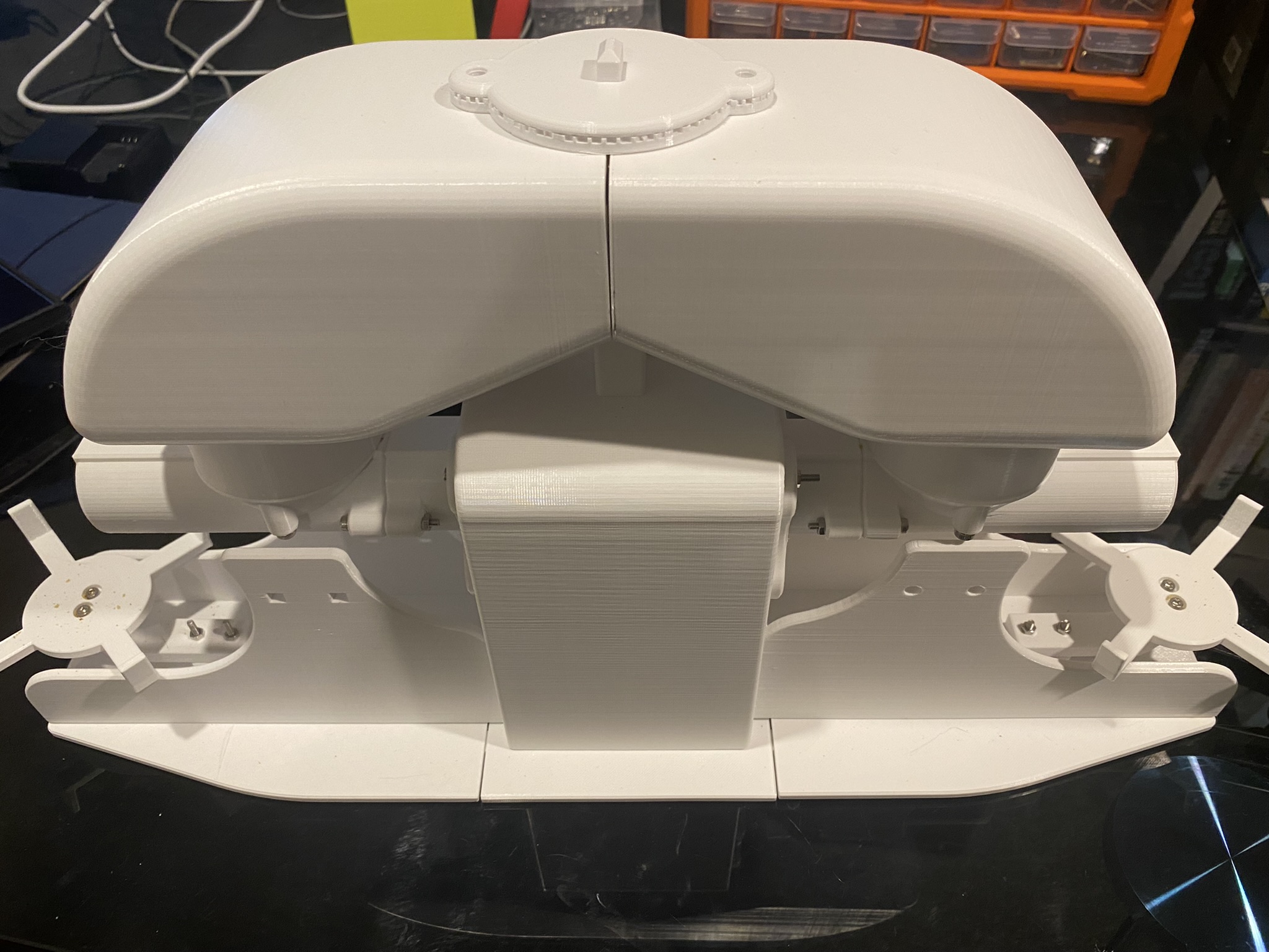
To simply describe what is built, the Feeder uses an Iot button click to trigger events over the internet to instruct the feeder to dispense food into one or both food bowls.
Here are some diagrams describing the architecture of the solution - the technical things that happens in-between the IoT button and the Cat Feeder.
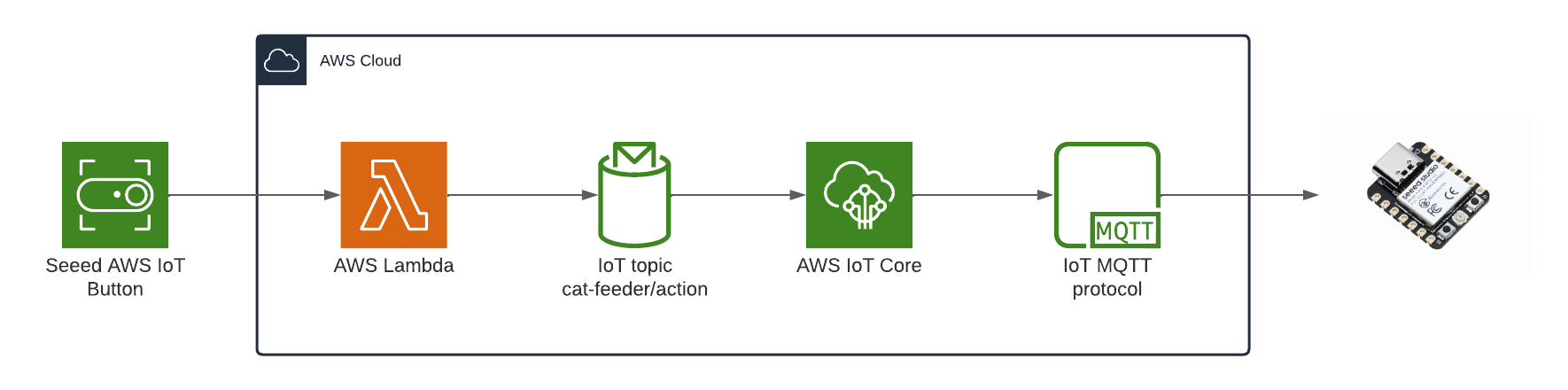
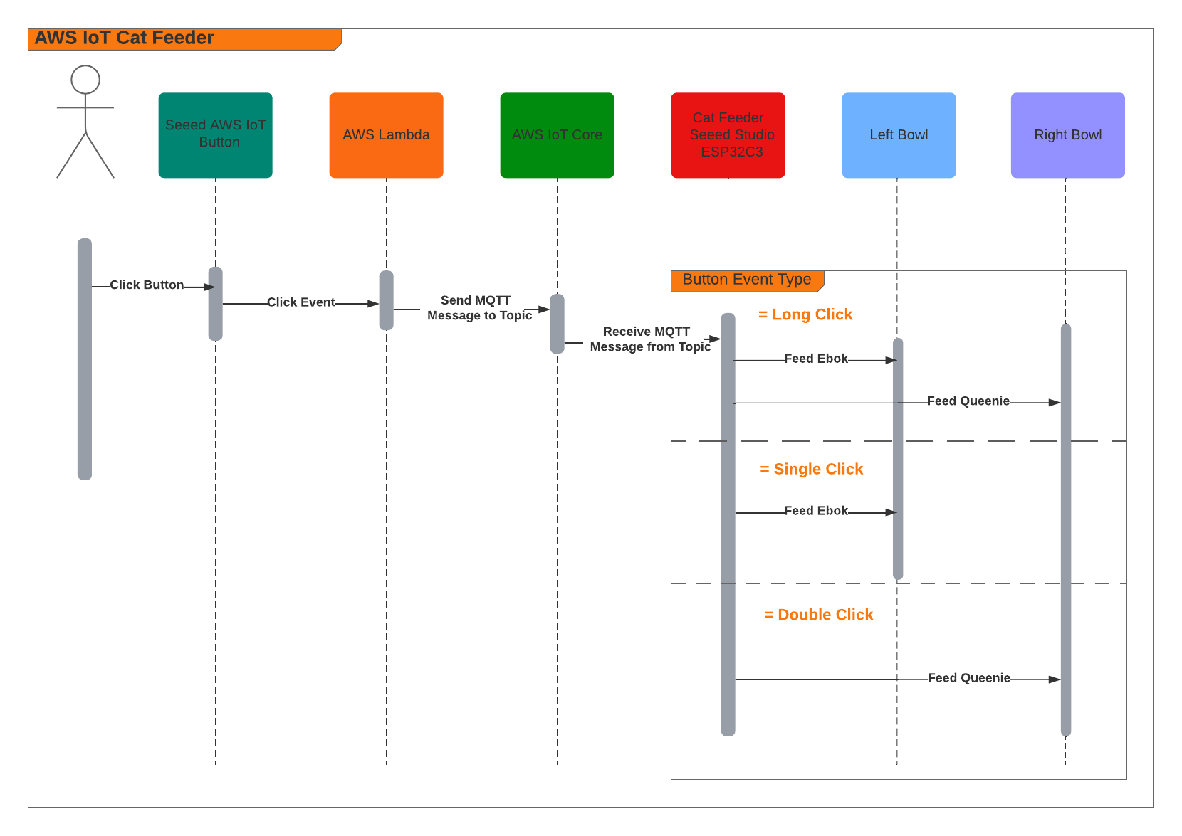
When the Feeder receives a MQTT message from the AWS IoT Core Service, it runs the motor for 10 seconds to dispense food into either one of food bowls, and if the message contains an event value to dispense food into both bowls we can run both motors concurrently using the L298N controller.
Here's a video of some timelapse picture captured during the 3 weeks it took to 3D print the feeder.
The Feeder is made up of a small handful of basic hardware components, below is a Breadboard diagram depicting the components used and how they are all wired up together. A regular 12V 2A DC power adapter supply is used to power all the components.
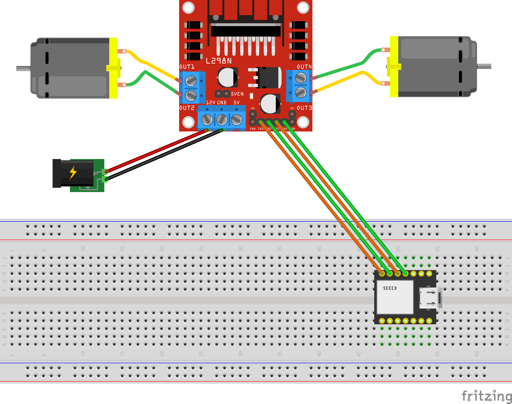
The code to start and stop a motor is about 10 lines of code as shown below. This is the completed version of the Arduino Sketch shown in Part 2 of this blog series when it was partially written at the time.
#include "secrets.h"
#include <WiFiClientSecure.h>
#include <MQTTClient.h>
#include <ArduinoJson.h>
#include "WiFi.h"

// The MQTT topics that this device should publish/subscribe
#define AWS_IOT_PUBLISH_TOPIC   "cat-feeder/states"
#define AWS_IOT_SUBSCRIBE_TOPIC "cat-feeder/action"

WiFiClientSecure net = WiFiClientSecure();
MQTTClient client = MQTTClient(256);

int motor1pin1 = 32;
int motor1pin2 = 33;
int motor2pin1 = 16;
int motor2pin2 = 17;

void connectAWS()
{
  WiFi.mode(WIFI_STA);
  WiFi.begin(WIFI_SSID, WIFI_PASSWORD);

  Serial.println("Connecting to Wi-Fi");
  Serial.println(AWS_IOT_ENDPOINT);

  while (WiFi.status() != WL_CONNECTED) {
    delay(500);
    Serial.print(".");
  }

  // Configure WiFiClientSecure to use the AWS IoT device credentials
  net.setCACert(AWS_CERT_CA);
  net.setCertificate(AWS_CERT_CRT);
  net.setPrivateKey(AWS_CERT_PRIVATE);

  // Connect to the MQTT broker on the AWS endpoint we defined earlier
  client.begin(AWS_IOT_ENDPOINT, 8883, net);

  // Create a message handler
  client.onMessage(messageHandler);

  Serial.println("Connecting to AWS IOT");
  Serial.println(THINGNAME);

  while (!client.connect(THINGNAME)) {
    Serial.print(".");
    delay(100);
  }

  if (!client.connected()) {
    Serial.println("AWS IoT Timeout!");
    return;
  }

  Serial.println("About to subscribe");
  // Subscribe to a topic
  client.subscribe(AWS_IOT_SUBSCRIBE_TOPIC);

  Serial.println("AWS IoT Connected!");
}

void publishMessage()
{
  StaticJsonDocument<200> doc;
  doc["time"] = millis();
  doc["state_1"] = millis();
  doc["state_2"] = 2 * millis();
  char jsonBuffer[512];
  serializeJson(doc, jsonBuffer); // print to client

  client.publish(AWS_IOT_PUBLISH_TOPIC, jsonBuffer);

  Serial.println("publishMessage states to AWS IoT" );
}

void messageHandler(String &topic, String &payload) {
  Serial.println("incoming: " + topic + " - " + payload);

  StaticJsonDocument<200> doc;
  deserializeJson(doc, payload);
  const char* event = doc["event"];

  Serial.println(event);

  feedMe(event);
}

void setup() {
  Serial.begin(9600);
  connectAWS();

  pinMode(motor1pin1, OUTPUT);
  pinMode(motor1pin2, OUTPUT);
  pinMode(motor2pin1, OUTPUT);
  pinMode(motor2pin2, OUTPUT);
}

void feedMe(String event) {
  Serial.println(event);

  bool feedLeft = false;
  bool feedRight = false;

  if (event == "SINGLE") {
    feedLeft = true;
  }
  if (event == "DOUBLE") {
    feedRight = true;
  }
  if (event == "LONG") {
    feedLeft = true;
    feedRight = true;
  }

  if (feedLeft) {
    Serial.println("run left");
    digitalWrite(motor1pin1, HIGH);
    digitalWrite(motor1pin2, LOW);
  }

  if (feedRight) {
    Serial.println("run right");
    digitalWrite(motor2pin1, HIGH);
    digitalWrite(motor2pin2, LOW);
  }

  delay(10000);
  digitalWrite(motor1pin1, LOW);
  digitalWrite(motor1pin2, LOW);
  digitalWrite(motor2pin1, LOW);
  digitalWrite(motor2pin2, LOW);
  delay(2000);

  Serial.println("fed");
}

void loop() {
  publishMessage();
  client.loop();
  delay(3000);
}
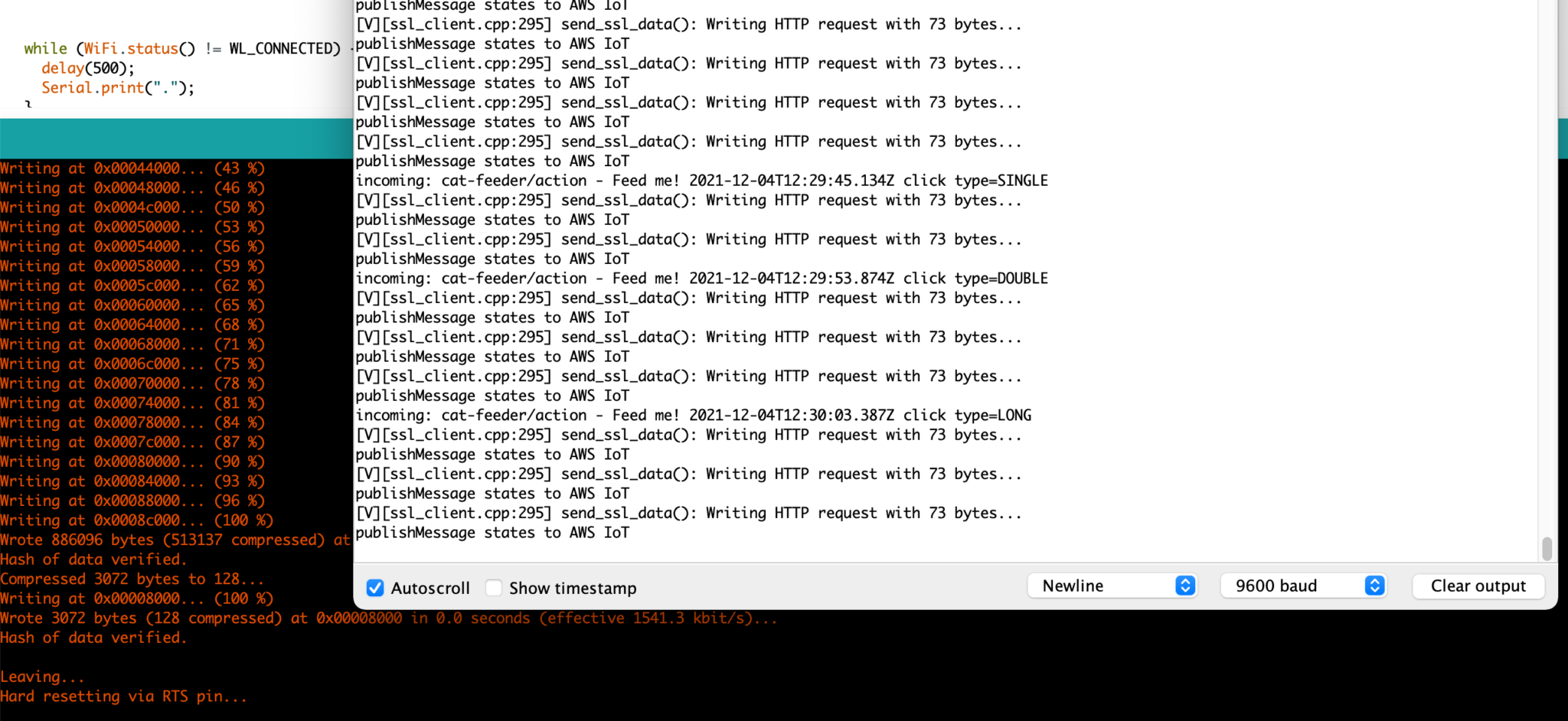
The Seeed AWS IoT Button is able to detect 3 different types of click events: Long, Single and Double, and we are able to leverage this all the way to the feeder so we will have it performing certains actions base on the click event type.
The video below demonstrates the following scenarios:
Build the nervous system of an ultimate nerd project I have in mind that would allow me to voice control actions controlling servos, LEDs and audio outputs, by using a mesh of Seeed XIAO BLE Sense micro-controllers and TinyML Machine Learning.
Recently, I was tasked with coming up with a solution for a single website instance to host various pockets of documentations scattered across a growing number of Git repositories; each repository hosted documentation for a specific subject domain written in Markdown format - you may have come across README.md files all over the internet which is a classic example of Markdown.
Here is a list of requirements based on what the solution has to solve:
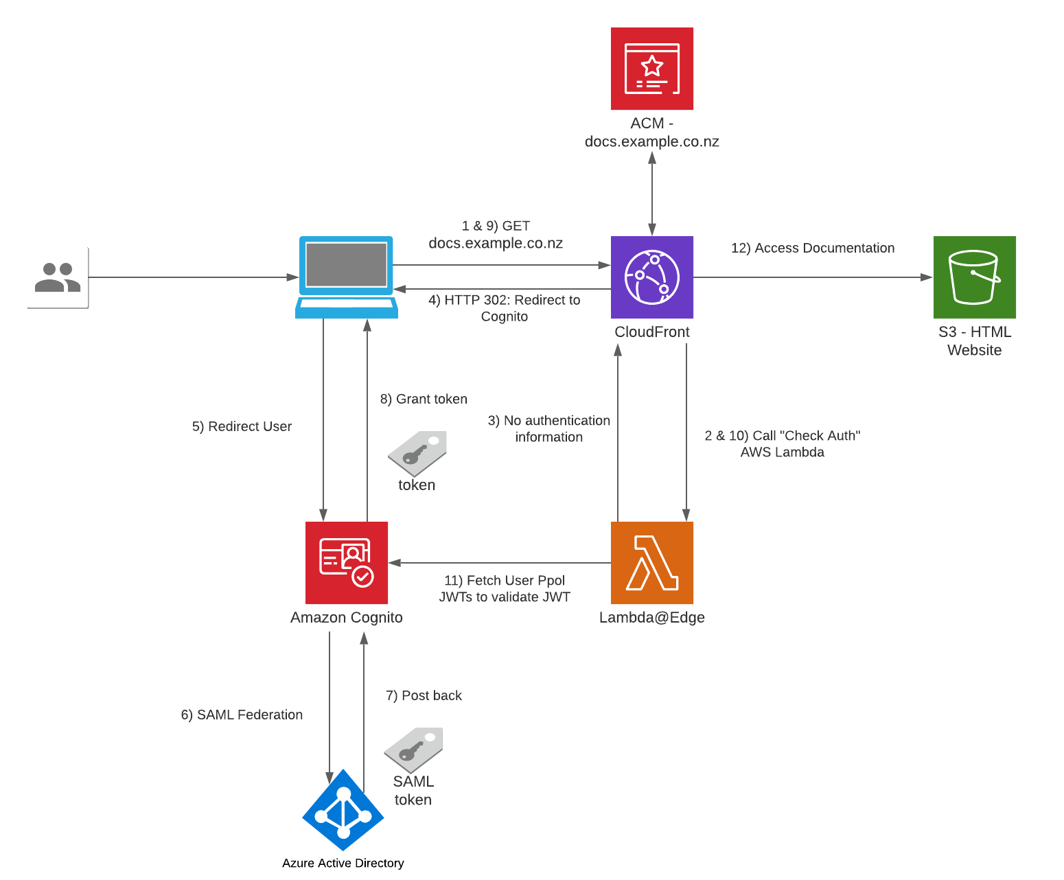
The Serverless Website Hosting Infrastructure I am about to talk about is built on top on an AWS's sample solution found here. I added resources on top of the example to suit our needs.
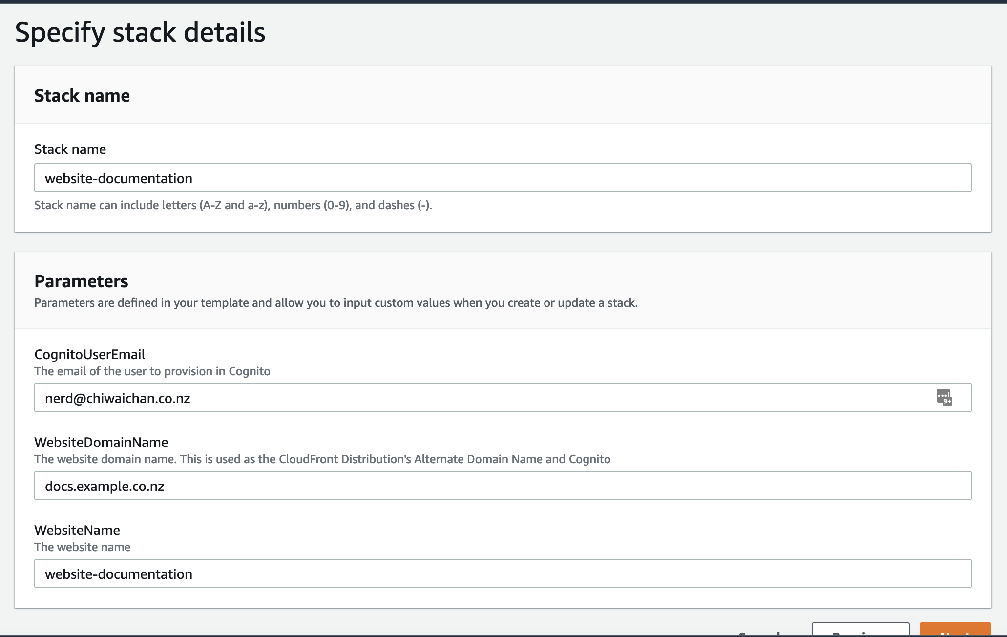
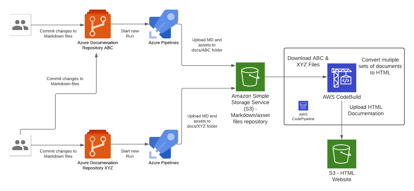
There are 2 types of pipelines that makes up the end-to-end pipeline for this solution, 1st type is for the Azure side to push Markdown files into AWS, the other is for AWS to compile the Markdown files and deploy them into S3 where the Website Content is hosted.
In the Azure pipeline we take the raw documentation (Markdown) from a Git repository hosted in Azure DevOps Git Repositories, each time a set code changes is pushed into any one of the Git repositories will trigger an Azure Pipeline "Run", the Azure Pipeline will upload the Markdown and assets files to a centralised S3 bucket repository (created by the Website Infrastructure CloudFormation Stack earlier).
Each Azure DevOps repository will host documentation for a specific domain topic, this Pipeline pattern is designed to cater for a growing number of repositories that has a requirement to host all documentations within a single Wesbite instance; the Azure Pipeline needs to be configured for each instance of Azure DevOps Git Repository. Once the Markdown files are converted to HTML during the CodeBuild stage of the CodePipeline execution, the output of those files are upload the S3 bucket that is served behind the CloudFront/Website stack.
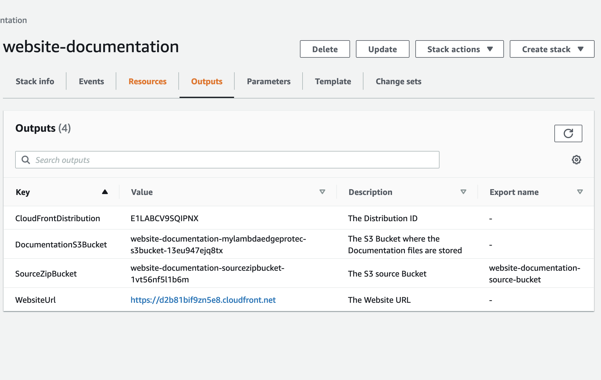
1 This step is skipped if the infrastruture website was previously set up for the another (first) set of documentation, in this case re-use the Access Keys created at that time in subsequent steps. Create a set of Access Keys for an AWS IAM User with a policy to perform the following actions on the "SourceZipBucket" bucket created in the Website Infrastructure CloudFormation stack earlier:
#example

{
"Version": "2012-10-17",
"Statement": [
  {
      "Sid": "VisualEditor0",
      "Effect": "Allow",
      "Action": [
          "s3:PutObject",
          "s3:GetObject",
          "s3:DeleteObject",
          "s3:ListBucket"
      ],
      "Resource": [
          "arn:aws:s3:::${REPLACE-WITH-SOURCE-ZIP-BUCKET-NAME}/*",
          "arn:aws:s3:::${REPLACE-WITH-SOURCE-ZIP-BUCKET-NAME}"
      ]
  },
  {
      "Sid": "VisualEditor1",
      "Effect": "Allow",
      "Action": "s3:ListAllMyBuckets",
      "Resource": "*"
  }
]
}
2 Create a new ADO pipeline from the existing YML file "templates/azure-pipeline.yml" in this repository.
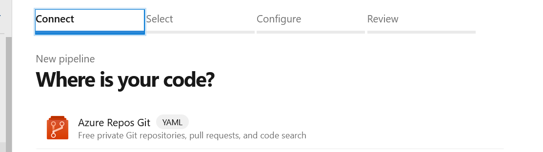
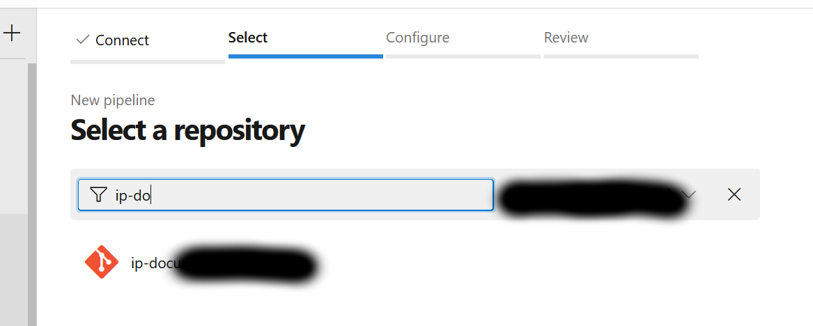
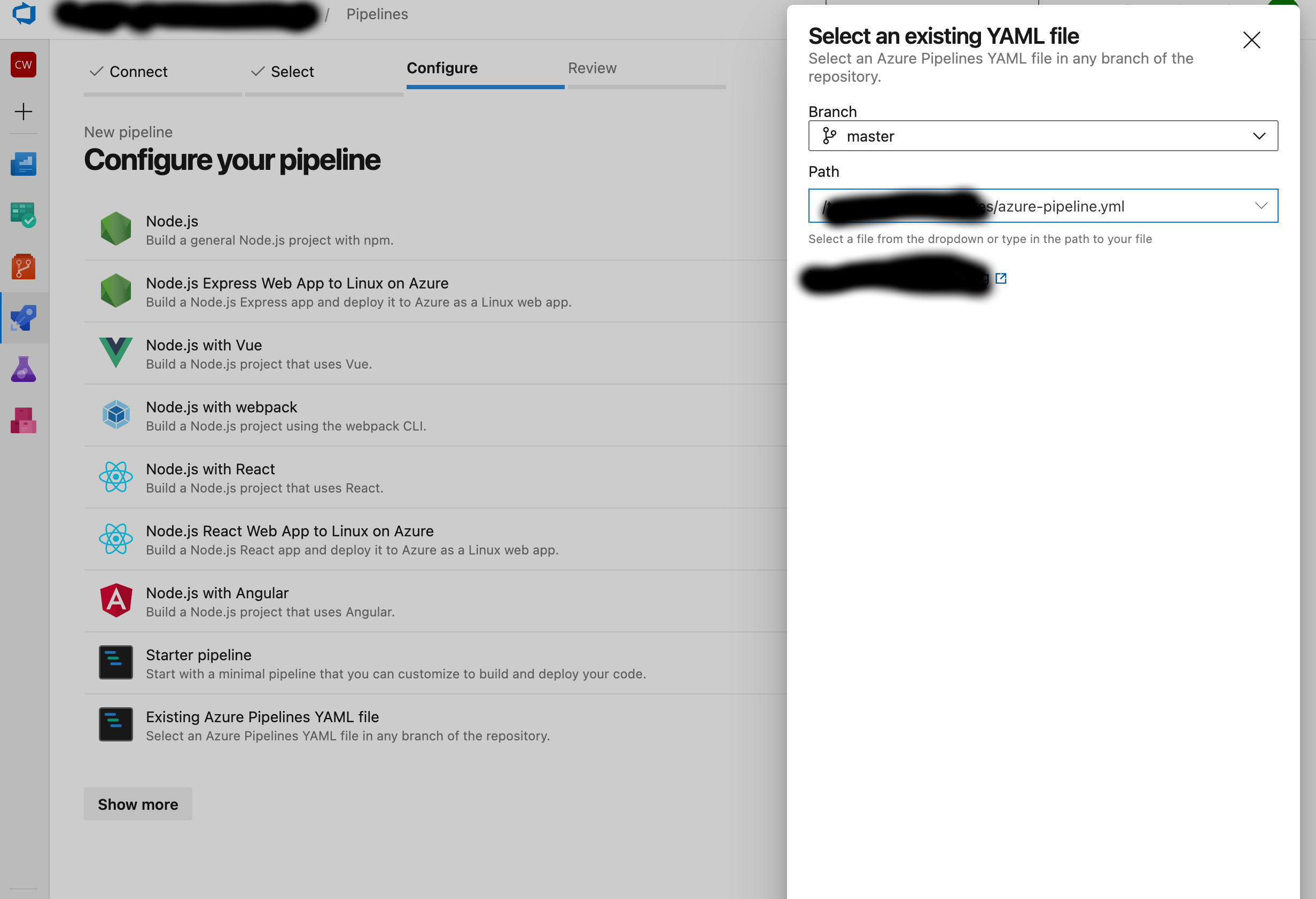
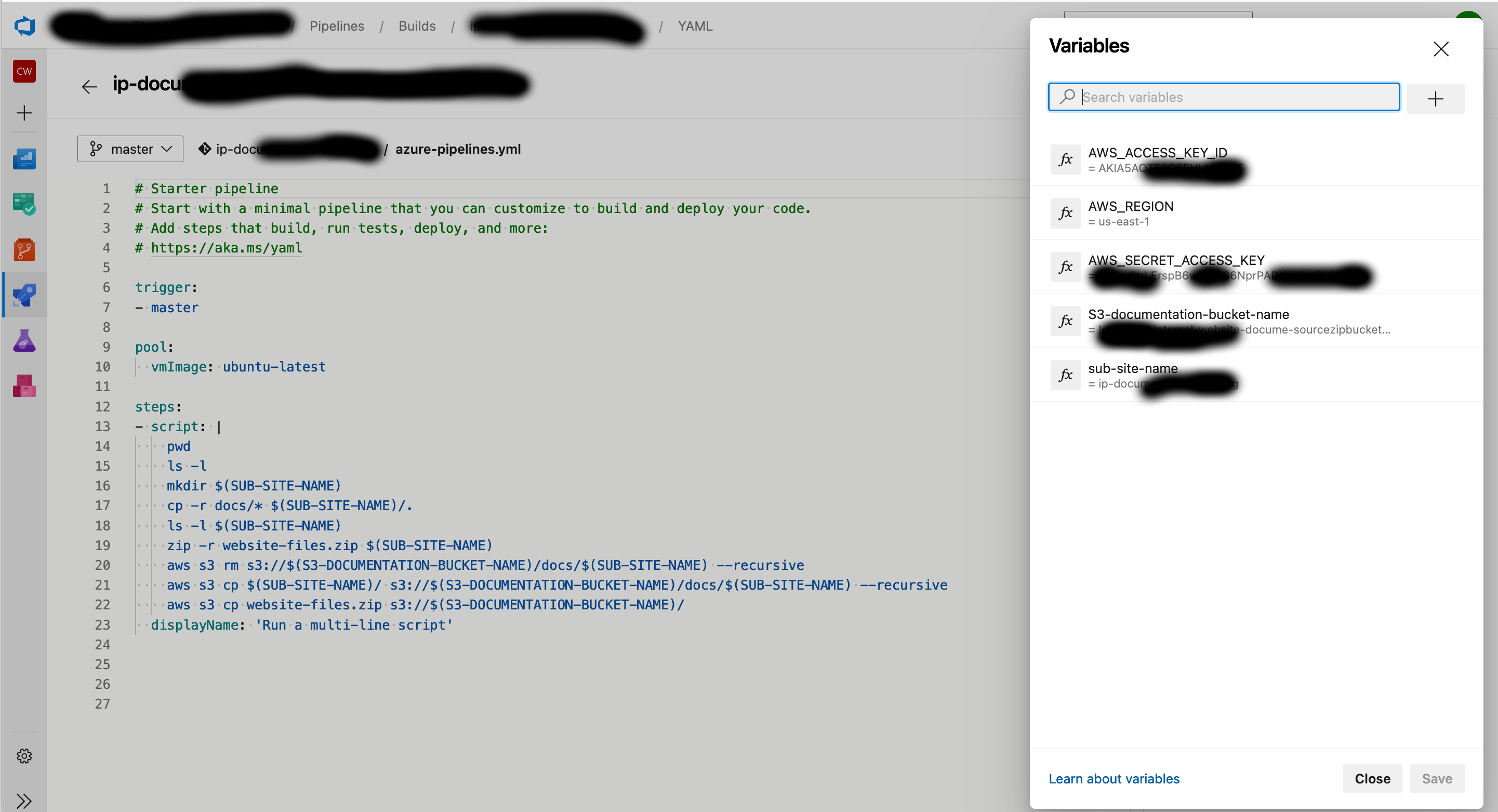
Use these as the variables for the Pipeline using the same case:
3 Hit Run to start a pipeline execution
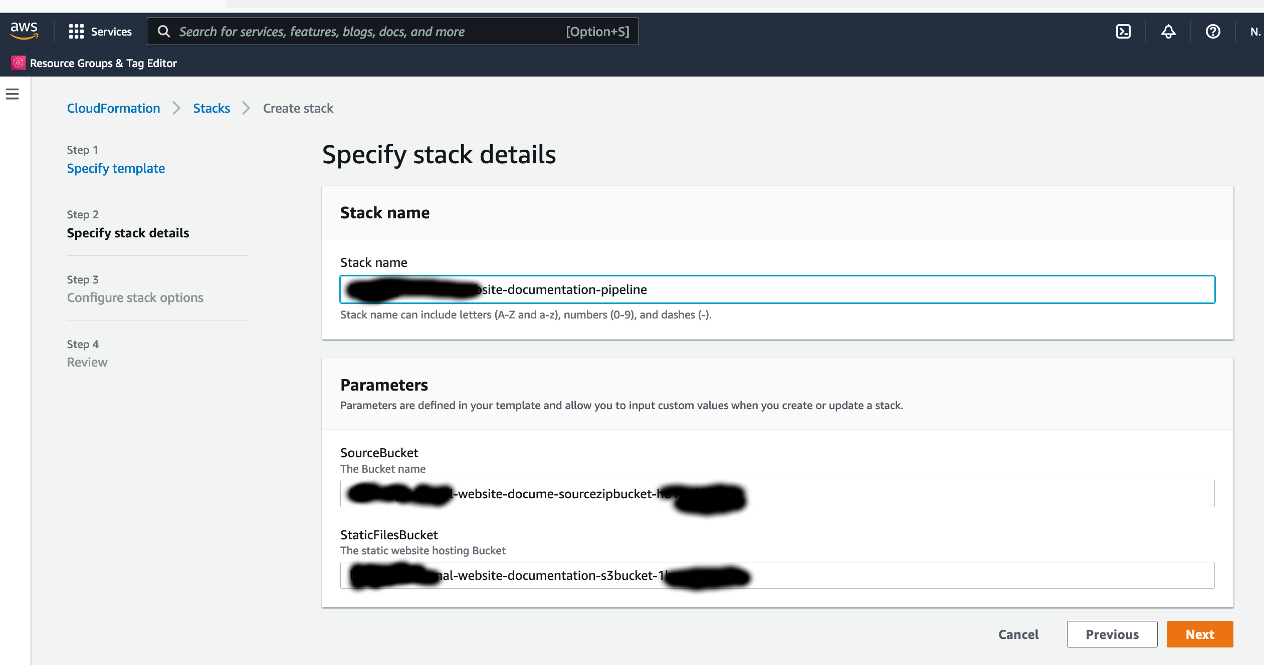
4 Skip this Step if you skipped Step 1. Create a CloudFormation stack for the Pipeline to deploy new Documentation, use the Cloudformation YML file "templates/aws-pipeline.yml" in this repository. Use the following as the Parameter values for the Pipeline:
The CodeBuild instance in the pipeline runs a set of commands that takes the Markdown and asset files, then produces as an output the HTML format equivalent files of the entire website for all sub-sites. In order for the CodeBuild instance to run successfully it expects the skeleton files in the root of the "DocumentationS3Bucket" S3 Bucket found in the Outputs of the Website Infrastructure CloudFormation Stack, this is so Docusaurus knows how to render the Markdown files into HTML.
To generate the skeleton files and upload it to the S3 bucket use the following commands on a local machine:
npx create-docusaurus@latest website classic
aws s3 cp website/. s3://${DocumentationS3Bucket}
The source code for this blog can be found in my Github repository: https://github.com/chiwaichan/aws-iot-cat-feeder. This repository only includes the source code for the solution implemented up to this stage/blog in the project.
In the end I decided to go with the Seeed Studio XIAO ESP32C3 implementation of the ESP32 micro-controller for $4.99 (USD). I also ordered some other bits and pieces from AliExpress that's going to take some time to arrive.
In this Part 2 of the blog series I will demonstrate the exchange of messages (JSON payload) using the MQTT protocol between the ESP32 and the AWS IoT Core Service, as well as the exchange of messages between a Lambda Function and the ESP32 - this Lambda is written in Python which is intended to replace the Lambda triggered by the IoT button event found in Part 1.
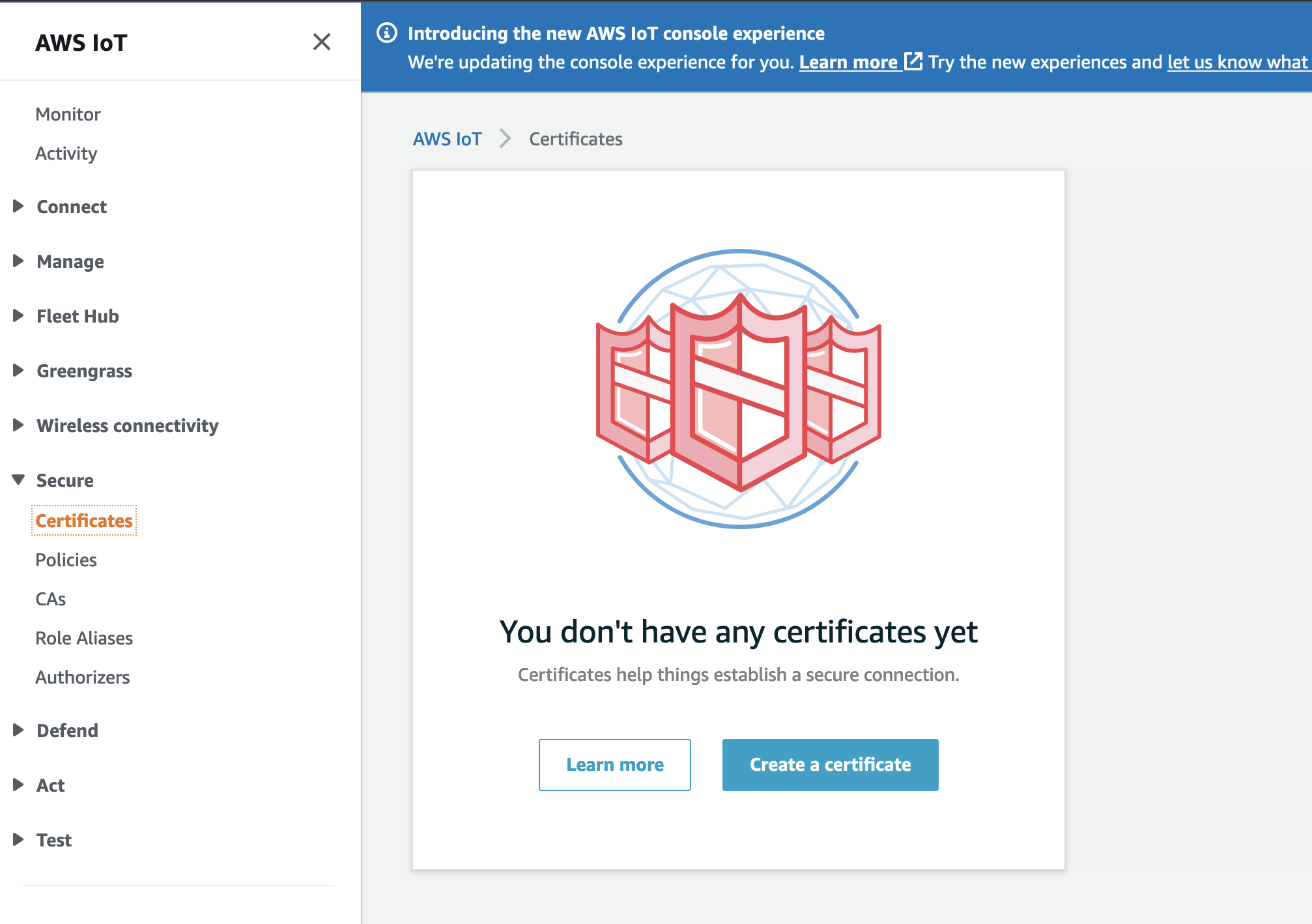
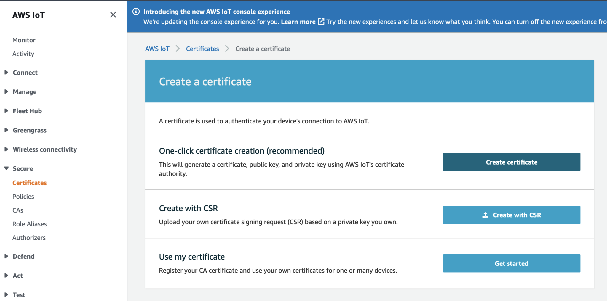
Create a Certificate using the recommended One-Click option.
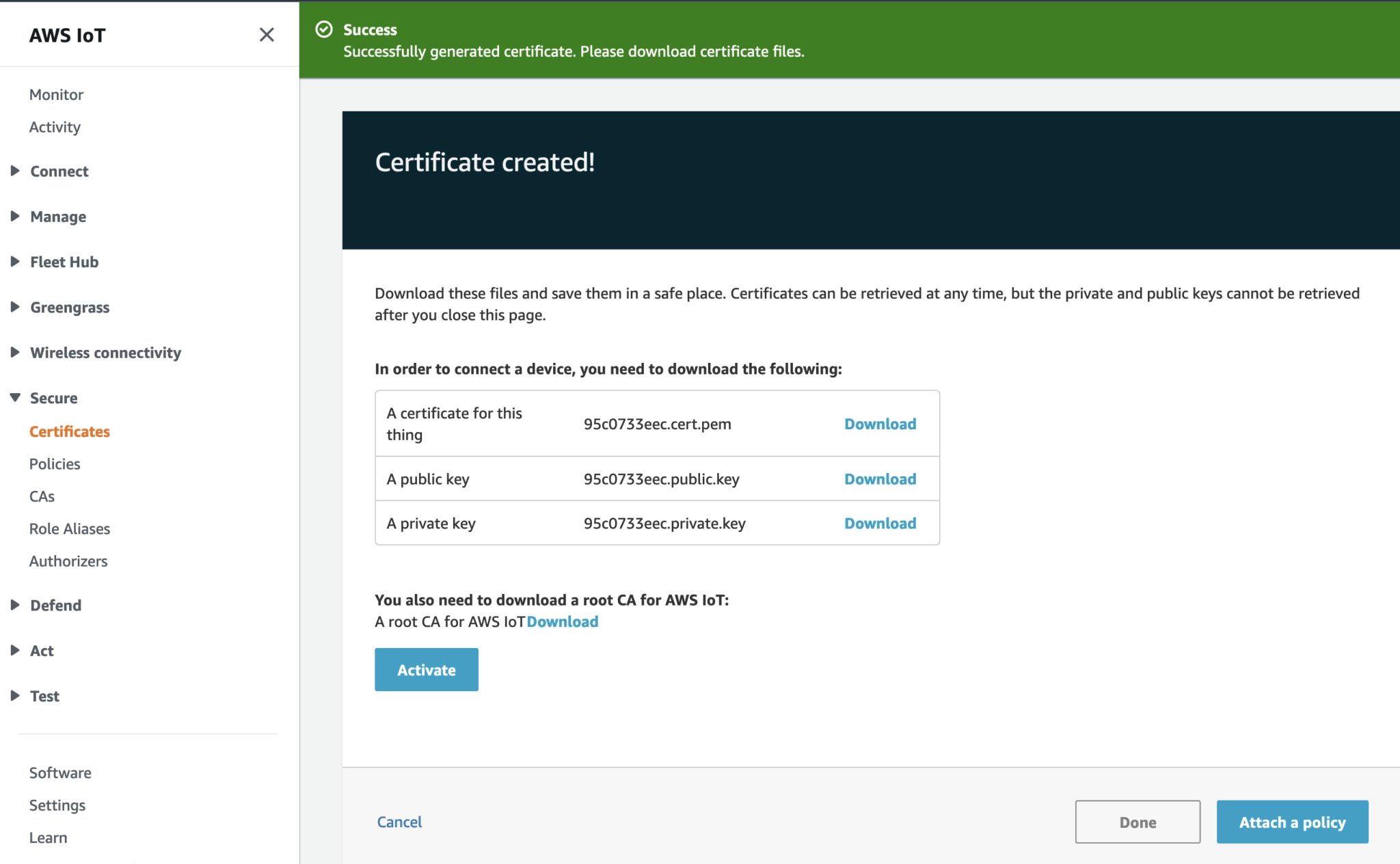
Download the following files and take note of which device (the ESP32 or the IoT Lambda) you like to use this certificate for:
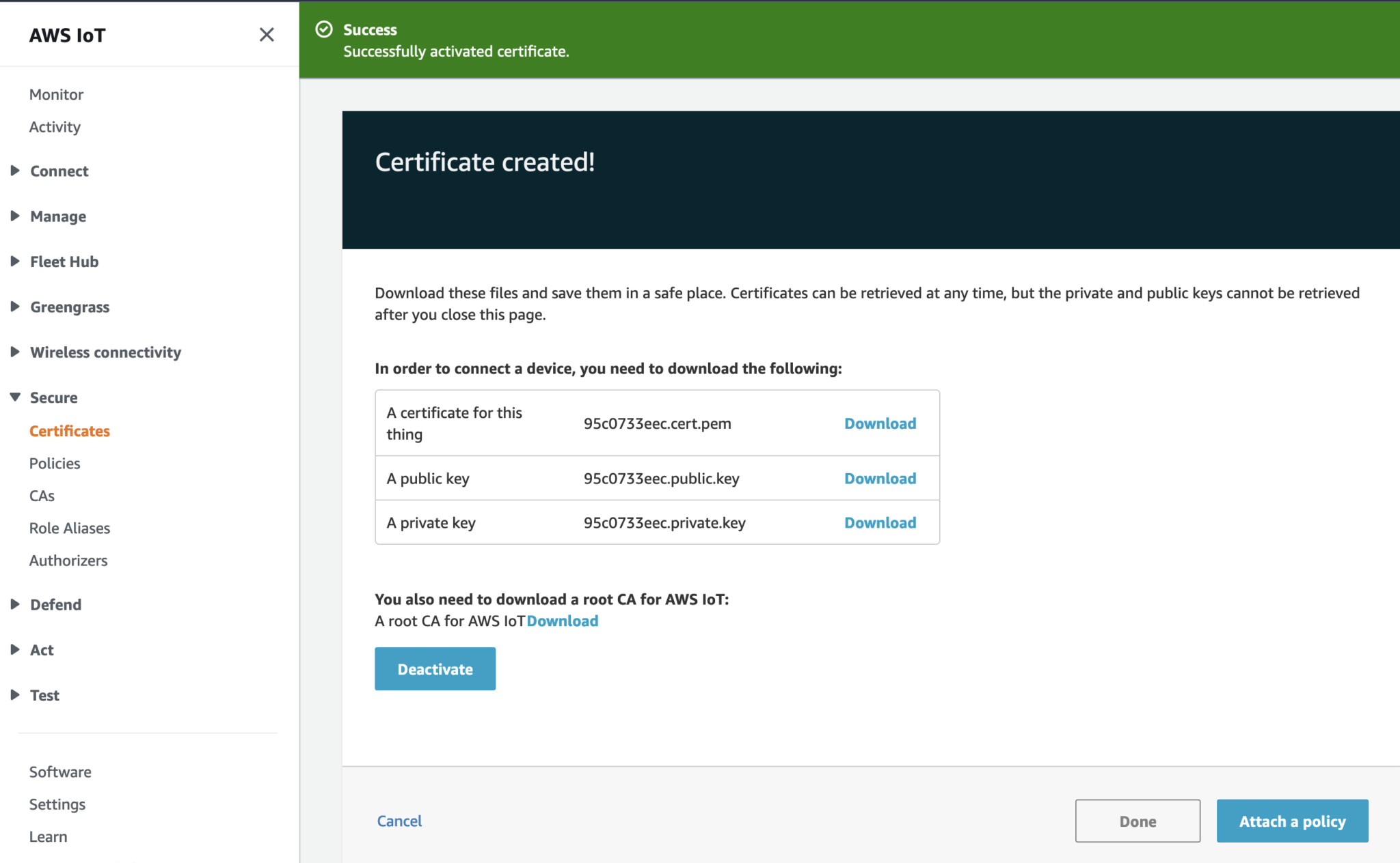
Activate the Certificate.
Click on Done. Then repeat the steps to create the second Certificate.
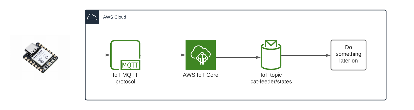
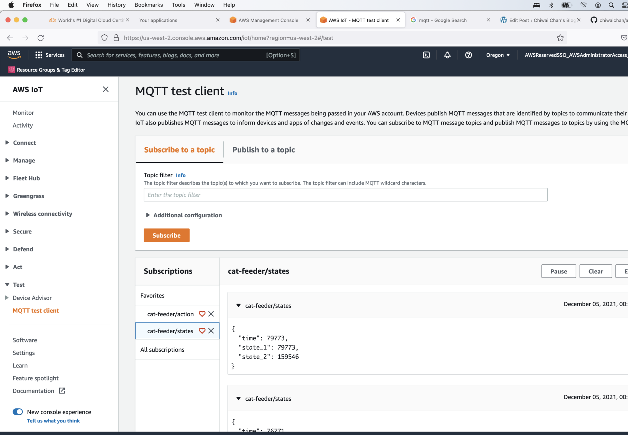
The diagram above depicts the components used that is required in order for the ESP32 to send the States of the Cat Feeder, I've yet to decide what to send but examples could be 1.) battery level 2.) Cat weight (based on a Cat's RFID chip and some how weighing them while they eat) 3.) or how much food is remaining in the feeder. So many options.
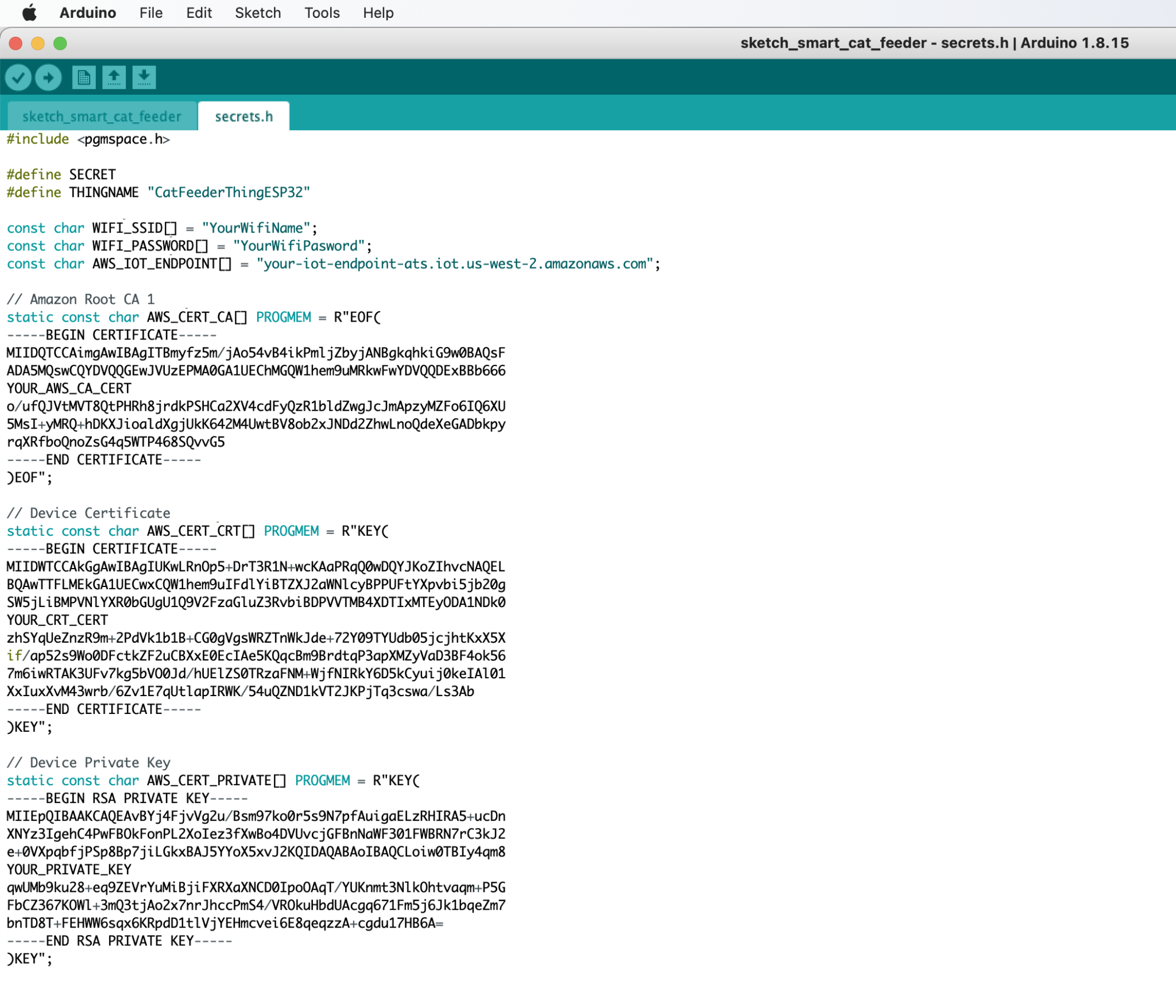
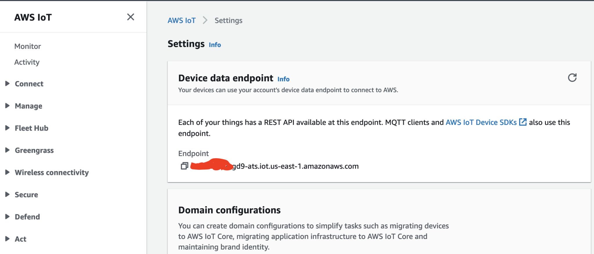
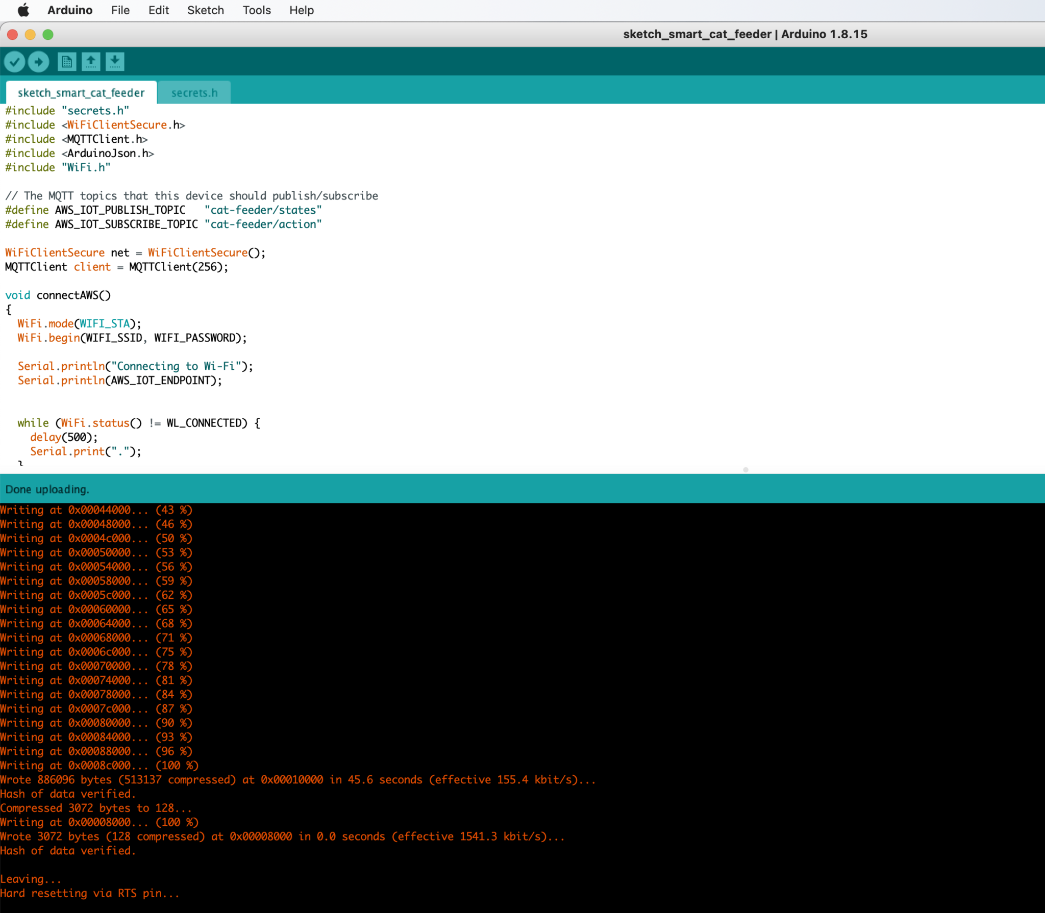
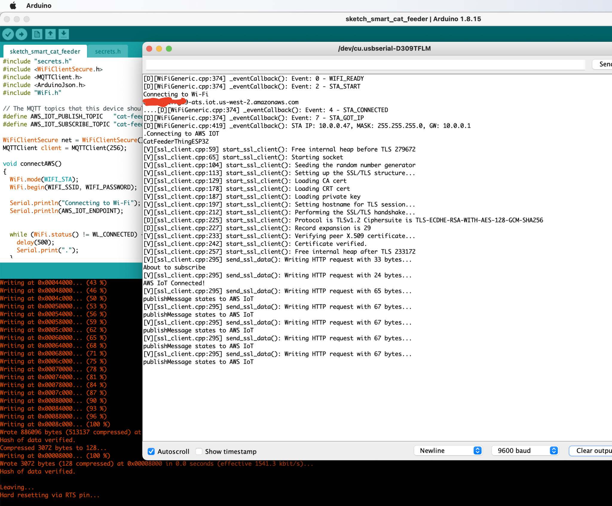
You might need to push a button on the micro-controller during the flashing process depending on the your ESP32 micro-controller
The diagram above depicts the components used to send a message to the ESP32 each time the Seeed AWS IoT button is pressed.
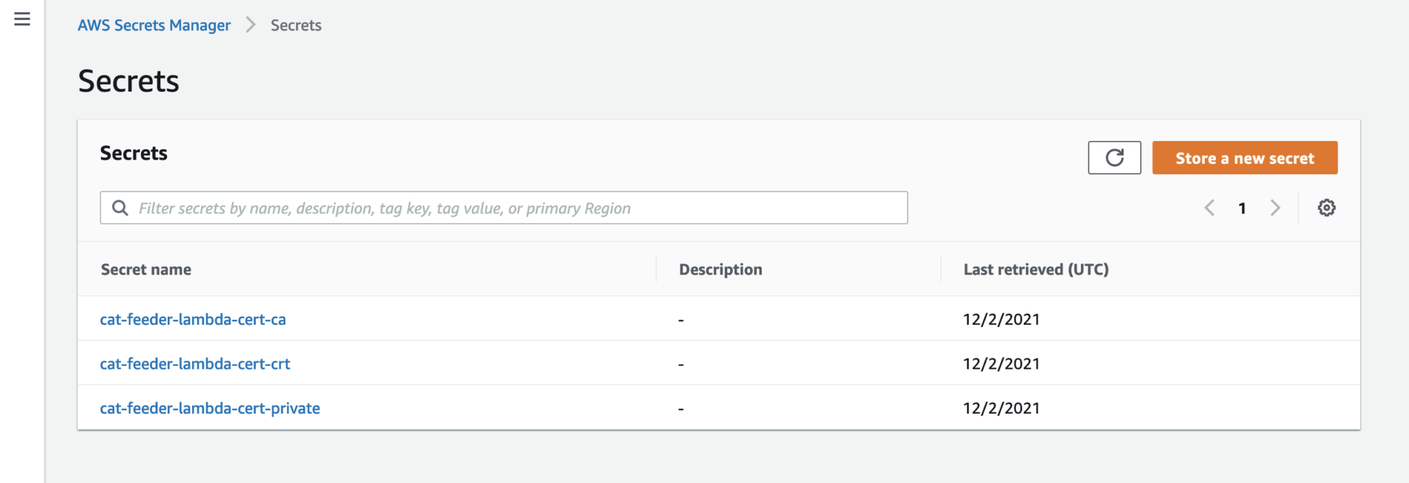
Get a copy of the AWS code from my Github repository: https://github.com/chiwaichan/aws-iot-cat-feeder
In a terminal go into the aws folder and run the commands found in the "sam-commands.text" file, be sure to replace the following values in the commands to reflect the values for your AWS account. This will create a CloudFormation Stack of the AWS IoT Services used by this entire solution.
I recently got a Creality3D Ender-3 V2 printer, I've got many known unknowns I know I need to get up to speed with in regards to fundamentals of 3D printing and all the tools, techniques and software associated with it. I'll attempt to print an enclosure to house the ESP32 controller, the wires, power supply/battery (if I can source a battery that lasts for more than a month on a single charge) and most importantly the dry cat food; I like to use some mechanical components to dispense food each time we press the IoT button described in Part 1. I'll talk in depth on the progress made on the 3D printing in Part 3.
If you are forgetful when it comes to feeding your fur babies like me, and you often only realise you need to put some dry food into the bowl when you are at work then you should read these series of blogs. Over time, I'll be designing and building a smart cat feeder over time using a combination of components such as Arduino micro controllers, motors, sensors and IoT devices and Cloud services. I'll publish the steps taken in these series of blogs, also, I'll publish any designs and source code as I figure things out and make decisions on aspects of the design.
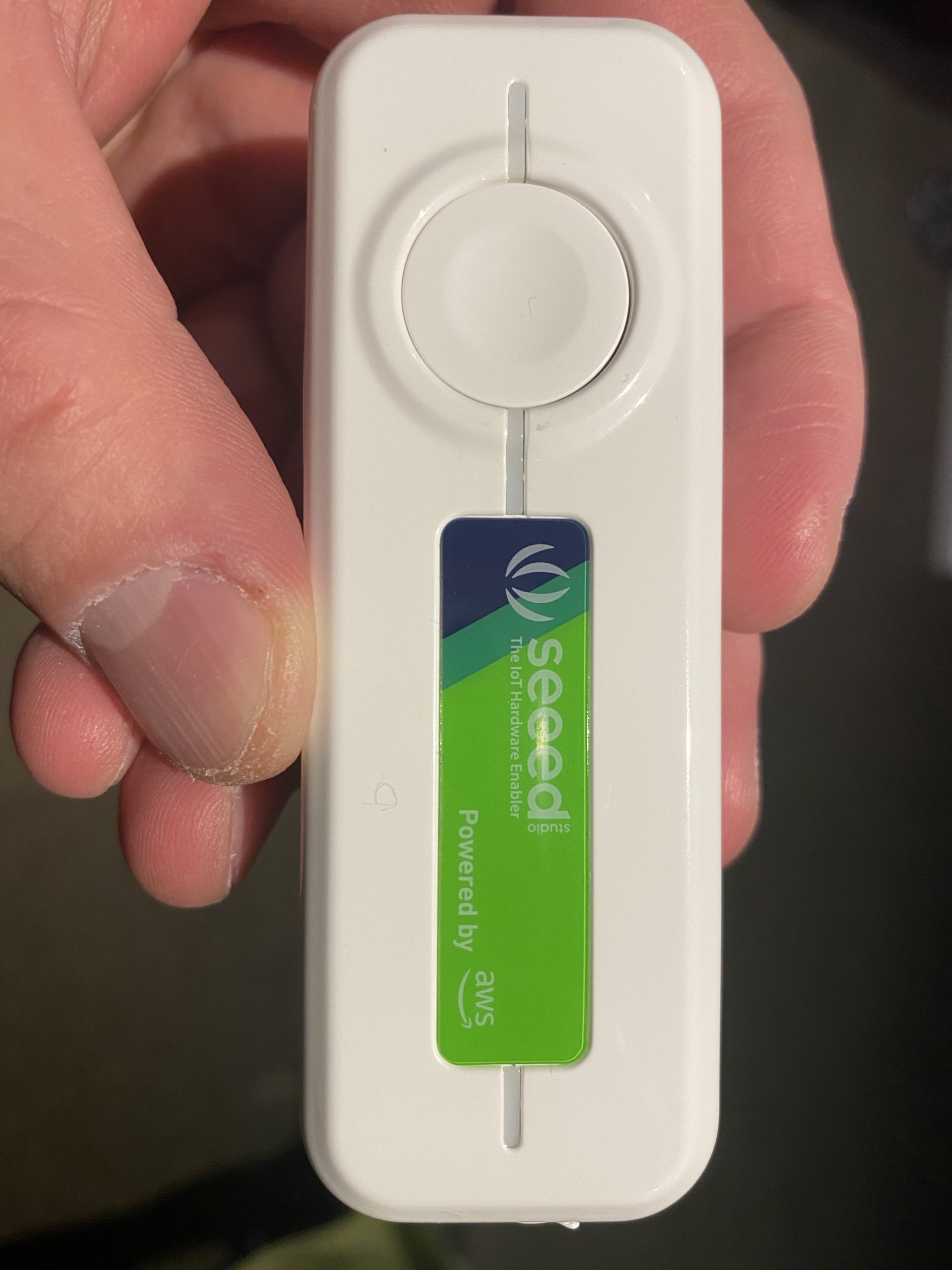
In this part 1 of the series, I will do a walkthrough on setting up an AWS IoT 1-Click device to trigger a Lambda Function. I got myself one of these Seeed IoT buttons for $20; I also bought a NCR18650B battery which I realised later on is only required if I wanted to run the device without it being powered by a USB type-C cable (used for charging the power as well).
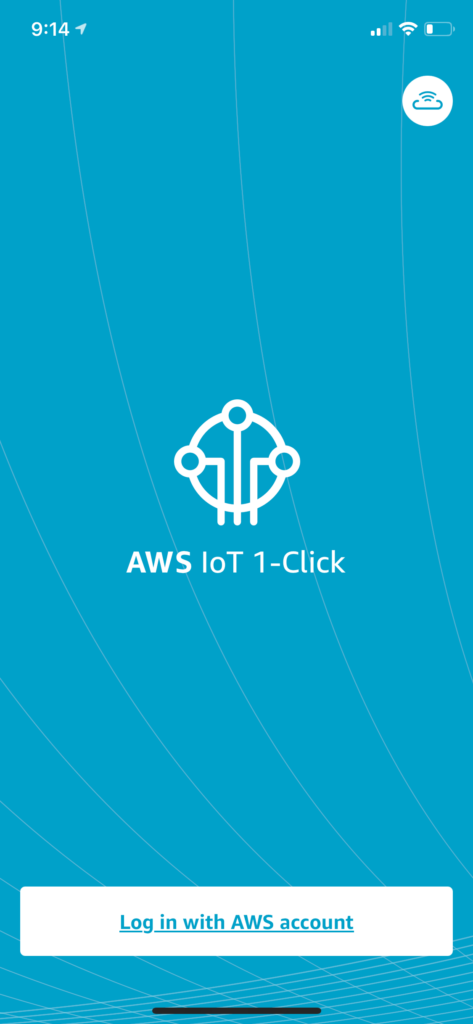
Firstly, make sure you have an AWS account. Then install the AWS IoT1-Click app onto your phone and log in using your AWS account. With these we will be able to link IoT devices up to our AWS account.
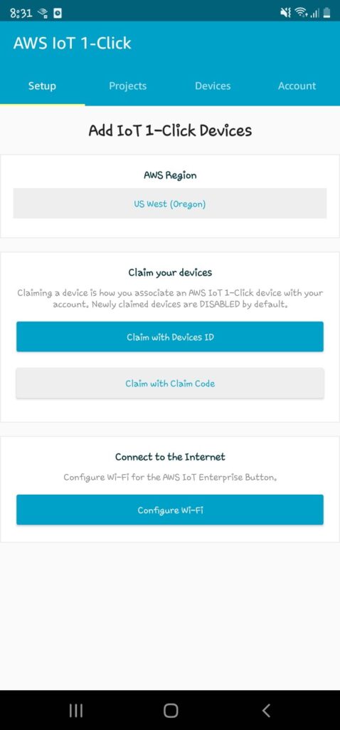
Claim the IoT device with Device ID
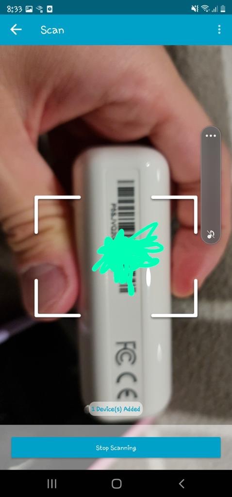
Scan the barcode on the back of the device; you can scan multiple devices in bulk.
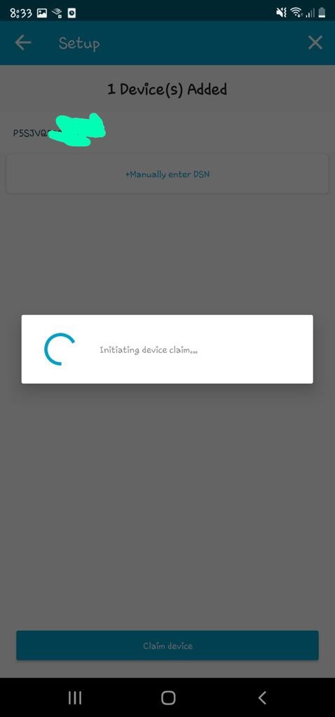
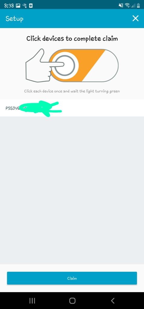
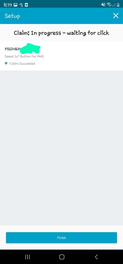
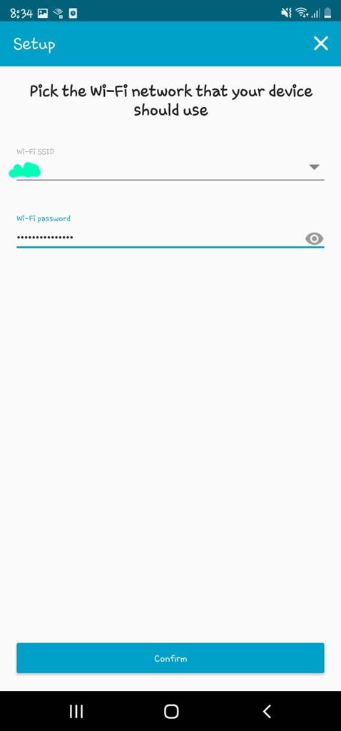
Next, I'll set up the Wifi on the device so that it can reach the internet internet from home. Can't see why I can't set it up to my phone's AP for feeding on the go, I'll try it out some other time.
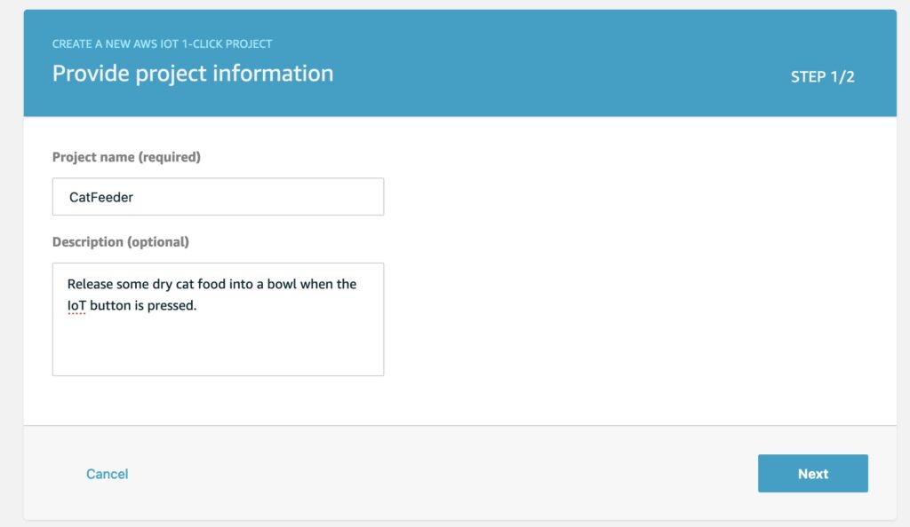
Now we'll create a project and add the IoT device to a placement group in the AWS Console. Give a name and description for the project.
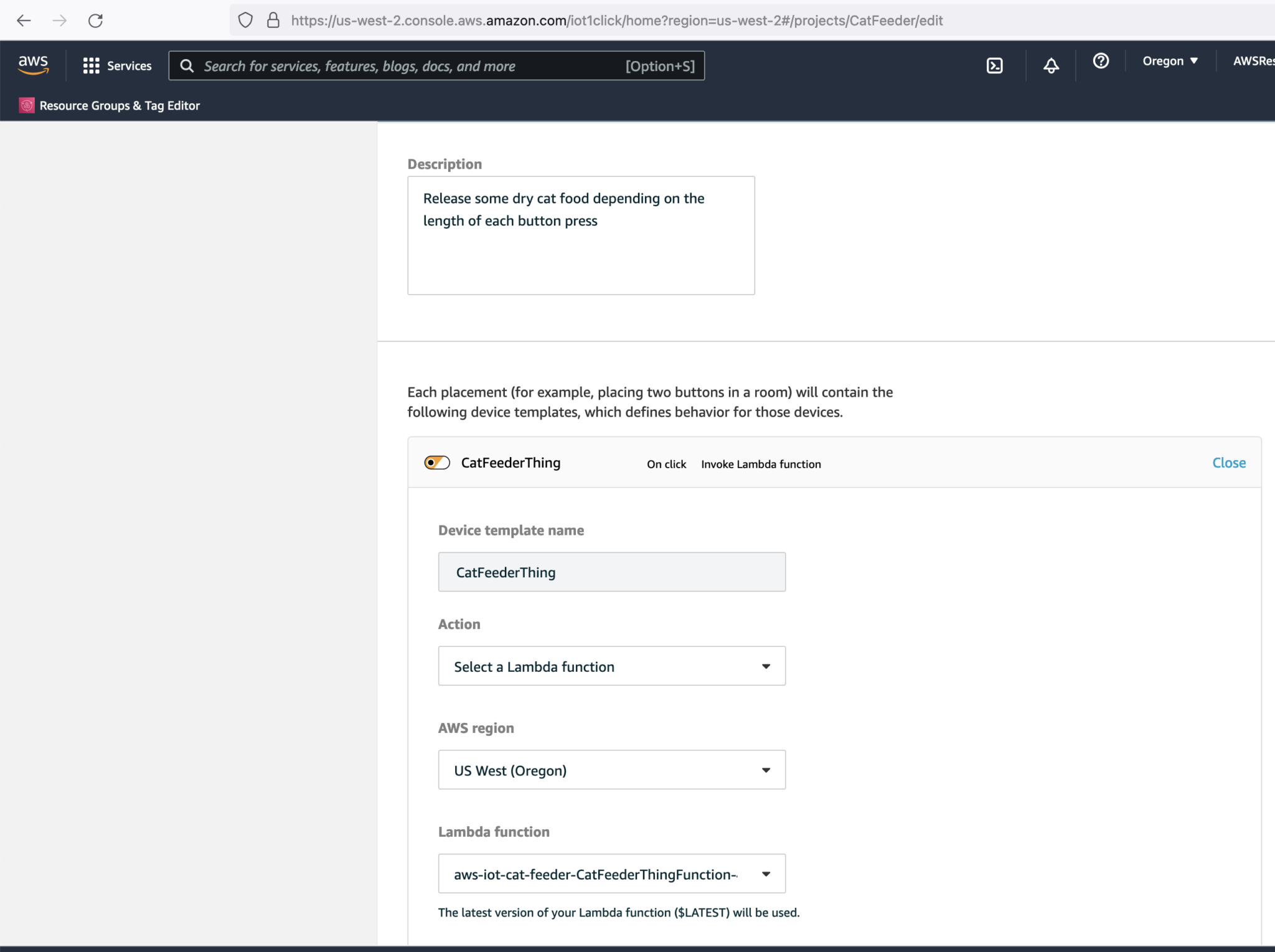
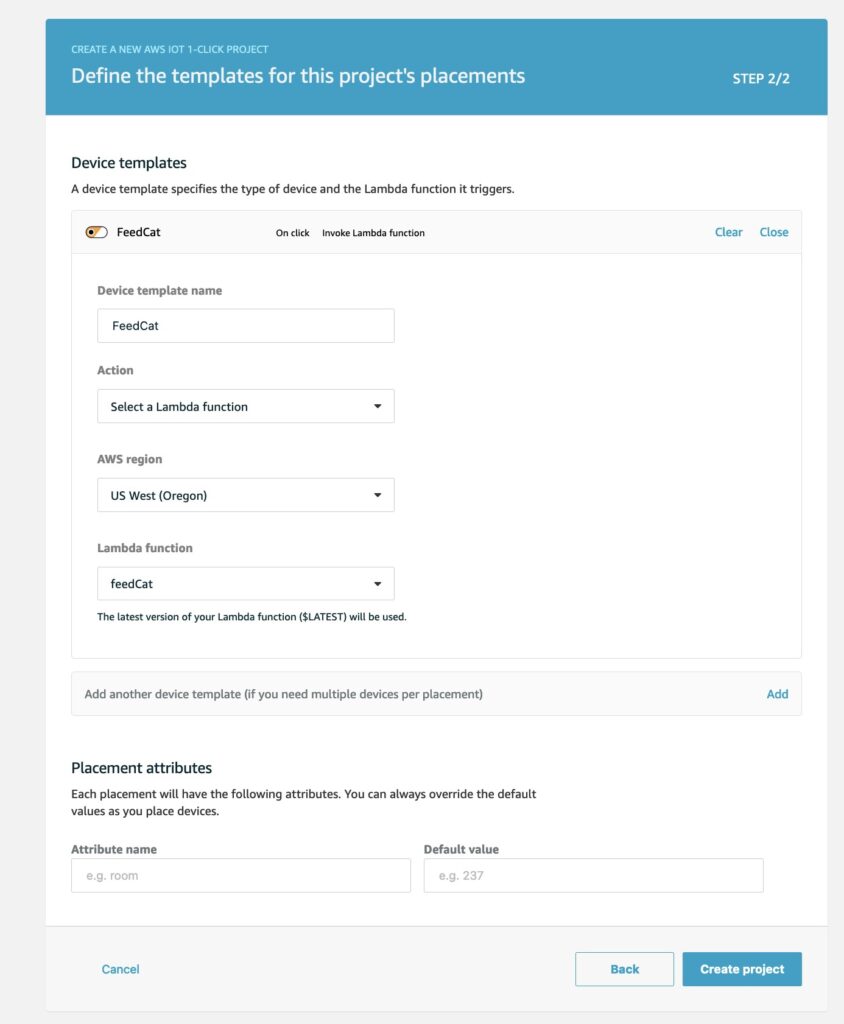
Next define a template, this is where we create a Lambda function; all the plumbing between the IoT device and Lambda will be handled for us.
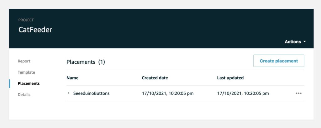
Next we create a placement for the Iot device.
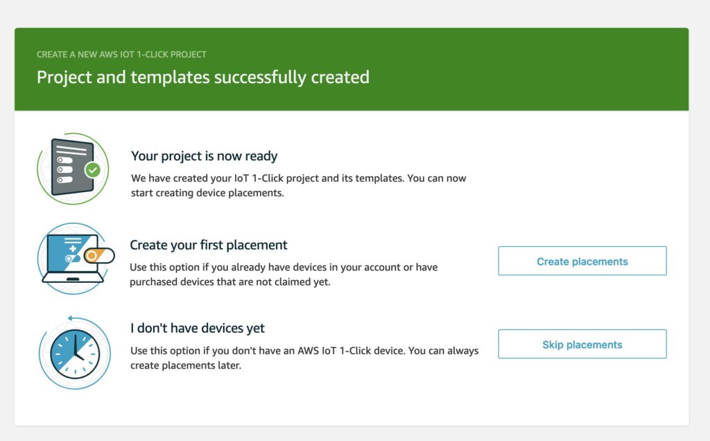
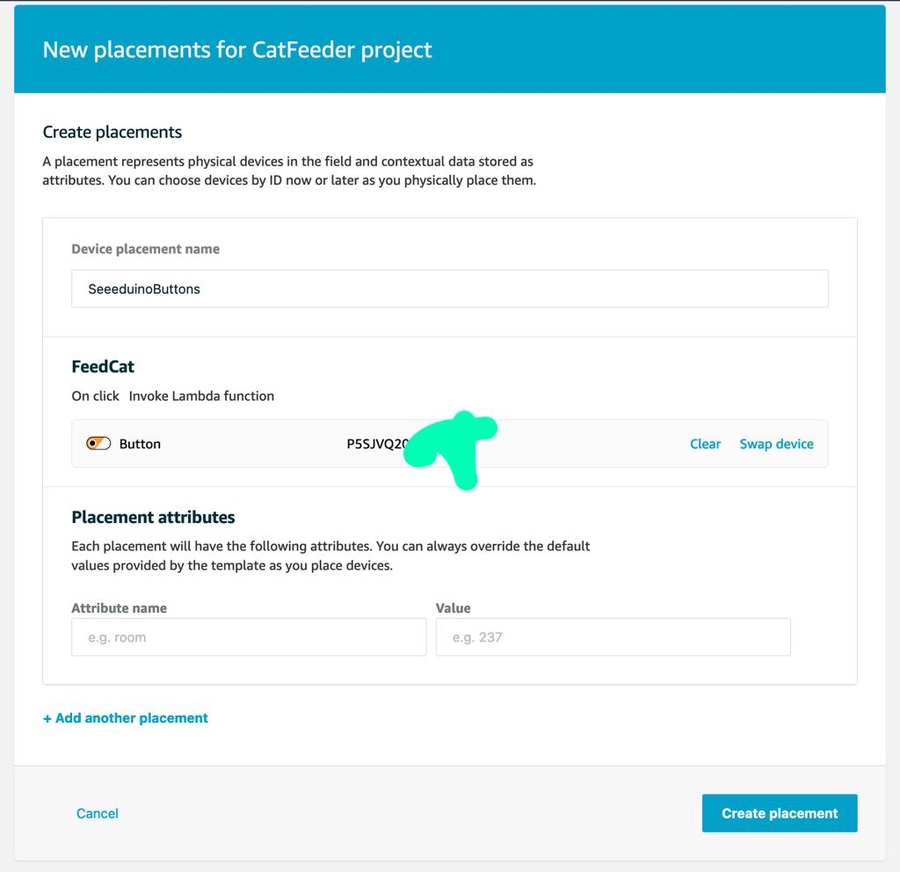
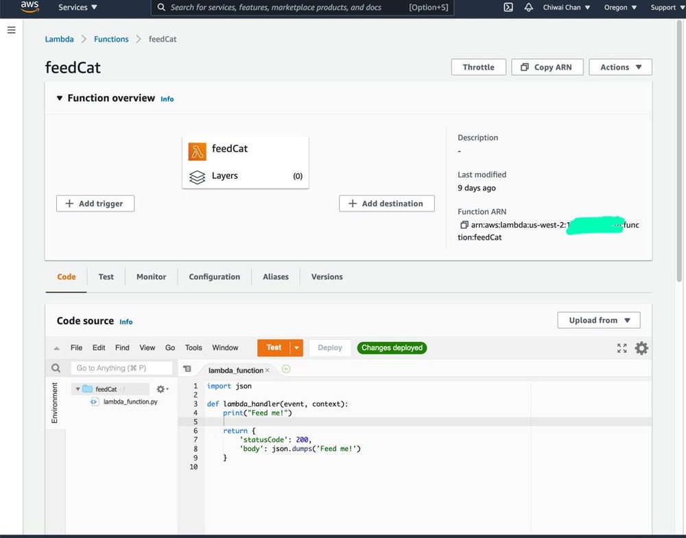
Since I have no Arduino micro-controllers (have yet to buy one), I will get the Lambda to log a message.
Push the button on the Iot device, wait for the event LED status to turn green after flashing white then check the logs CloudWatch Logs.
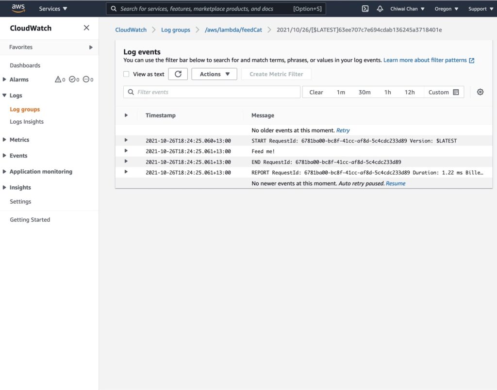
At some point I have to code the Lambda to perform a real action as each event comes through, which will be demonstrated in a following blog in the series instead of just logging to CloudWatch logs.
Within the app on your phone you can see status of each IoT device such as the remaining battery life percentage.
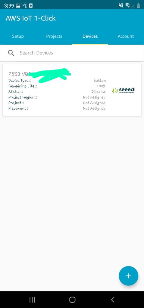
As well as a history of the button's events.
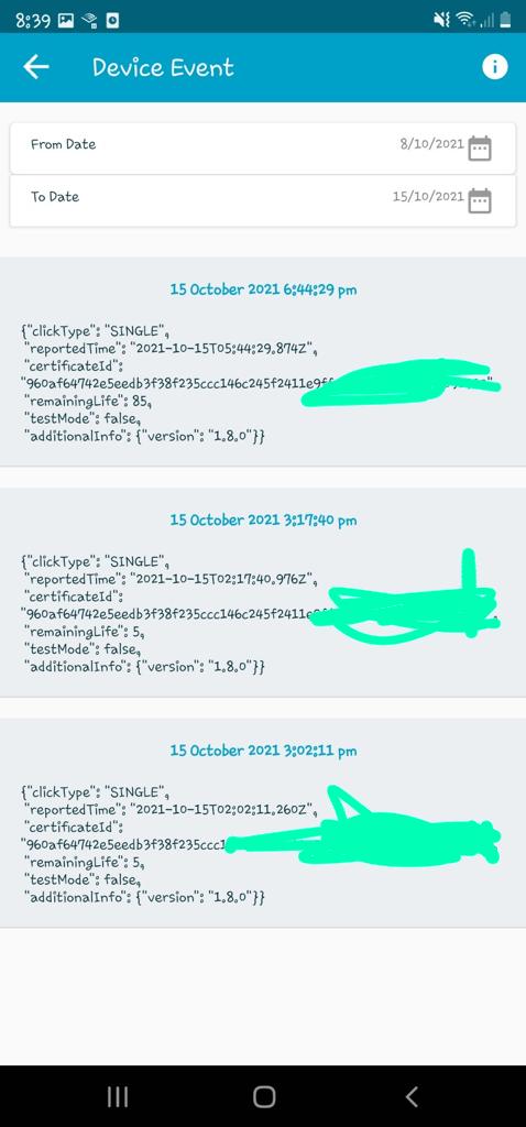
In the next blog, I'll configure the Lambda to push the event to a Topic for AWS IoT Core to subscribe to, which in turns will trigger an event to an ESP32 ( I've yet to decide on a specific version of the micro-controller) using the IoT MQTT protocol.